close
Choose Your Site
Global
Social Media
Views: 0 Author: Site Editor Publish Time: 2026-10-12 Origin: Site
In industrial dust collection and baghouse systems, filter cleaning reliability hinges directly on compressed air delivery precision. Operating outside the optimal pulse valve working pressure leads to cascading mechanical failures. Low pressure causes insufficient cleaning and filter blinding. Excessive pressure accelerates component wear, ruptures diaphragms, and degrades filter bags. Selecting the right Pulse Valve requires a rigorous evaluation of operating limits, system pressure stability, and specific pneumatic demands. This guide breaks down the technical parameters for evaluating and optimizing pressure dynamics. We outline how to maintain peak baghouse efficiency while protecting your pneumatic infrastructure from premature fatigue.
Optimal Ranges Vary by Design: Standard pulse valves typically operate between 0.3 to 0.8 MPa (40–115 psi), but submerged or specialized low-pressure valves require distinct header configurations to function reliably.
Stability Over Peak Pressure: Consistent pressure recovery between pulse cycles is more critical to baghouse efficiency than achieving maximum peak pressure.
Response Time is Pressure-Dependent: The crispness of the shockwave relies on millisecond opening and closing times, which are directly dictated by maintaining the correct working pressure.
Air Quality Dictates Pressure Reliability: Moisture and particulate contamination in the compressed air supply drastically alter the effective working pressure and degrade diaphragm responsiveness.
Table of Contents
Defining the correct pressure involves balancing effective particulate dislodgement with system integrity. You must generate enough force to clear the dust cake without exceeding the mechanical limits of the filter media. Understanding this balance forms the foundation of baghouse optimization. Field technicians often rely on gauge readings at the compressor, but the only metric that matters is the actual pressure delivered at the header tank during actuation.
The optimal pulse valve working pressure depends on valve design, manufacturer specifications, and dust collector cleaning requirements. Some industrial pulse valves operate within a range of approximately 0.3–0.8 MPa, but this is not a universal operating standard.
According to the U.S. EPA's guidance on pulse-jet fabric filter operation, pulse-jet collectors use short bursts of compressed air to remove accumulated dust from filter bags.
Engineers should adjust operating pressure and pulse duration based on valve specifications, dust characteristics, filter differential pressure, and compressed air consumption.
Diaphragm actuation relies entirely on pilot pressure differentials. Compressed air fills the chamber above the main diaphragm. This equalized pressure holds the valve closed. When the pilot solenoid energizes, it vents this upper chamber. The sudden pressure drop allows the air below to lift the diaphragm. This releases the main blast of air into the blowpipe.
Millisecond response times are critical for effective cleaning. Optimal pulse valve working pressure ensures a rapid, crisp shockwave. If pressure is too low, the diaphragm lifts sluggishly. This results in a slow release of air rather than a sharp blast. A sluggish pulse fails to induce the necessary Venturi effect inside the filter bag. Dust remains trapped on the media.
Bleed holes control the equalization of pressure. After the pilot closes, air flows through the bleed hole to refill the upper chamber. This forces the diaphragm back down to seal the valve. If the bleed hole is partially blocked, closing time extends. This wastes massive amounts of compressed air and prevents the header tank from recovering for the next cycle.
Maintaining minimum working pressure is absolutely non-negotiable. The diaphragm relies on a combination of air pressure and spring tension to seal. If system pressure drops below the minimum threshold, the valve will not close. It will remain stuck open, continuously venting your compressed air supply.
Pulse valve size and flow coefficient (Cv) determine the volume of compressed air delivered during cleaning. Larger valves provide higher airflow but require sufficient header tank capacity to maintain stable pressure. Properly matching valve size, operating pressure, and manifold volume helps prevent pressure loss, improve cleaning efficiency, and reduce unnecessary air consumption.
Pulse valves must operate within manufacturer-specified pressure limits to ensure reliable cleaning and prevent equipment damage. Both insufficient and excessive pressure can reduce system performance, increase maintenance requirements, and shorten component service life.
Insufficient operating pressure can cause weak cleaning pulses, incomplete diaphragm actuation, and unstable valve operation. Poor cleaning allows dust to accumulate on filter bags, increasing differential pressure and reducing airflow. Regularly monitoring header pressure, checking for air leaks, and verifying supply capacity help maintain reliable cleaning performance.
Excessive operating pressure increases mechanical stress on valve diaphragms, seals, and filter media. Strong cleaning pulses may accelerate filter wear, damage bag seams, and waste compressed air. Maintaining pressure within the recommended range helps protect components, reduce energy consumption, and extend dust collector service life.
Stable pressure delivery determines the long-term reliability of your dust collection system. Erratic pressure causes erratic cleaning. Some rows of bags get cleaned perfectly, while others remain blinded. You must engineer your pneumatic supply to guarantee consistent pressure recovery between every single pulse.
Undersized compressed air supply lines are a primary culprit. If the pipe feeding the header tank is too narrow, it restricts flow. The compressor may have adequate capacity, but the air cannot reach the tank fast enough. This starves the Pulse Valve during operation.
Rapid sequential pulsing prevents adequate recovery time. If the controller fires valves too quickly, the header tank never refills. The first valve fires at 0.6 MPa. The second fires at 0.4 MPa. The third fails to open entirely. You must program sufficient delay between actuations.
Friction losses in piping networks also cause fluctuations. Long pipe runs, excessive elbows, and restrictive fittings reduce the delivered pressure. The pressure at the compressor room does not equal the pressure at the baghouse header. You must measure pressure directly at the point of use.
Proper header tank sizing helps maintain adequate compressed air storage and stable pressure during pulse cleaning. The manifold should provide sufficient air volume, minimize pressure fluctuations, and distribute compressed air consistently across multiple valves.
Where applicable, compressed air receivers must comply with relevant pressure equipment safety requirements. The OSHA compressed air receiver safety requirements (29 CFR 1910.169) address pressure gauges, safety valves, drainage, and other installation considerations.
The applicability of specific pressure vessel standards should be confirmed according to the equipment design, installation location, and local regulations.
Pressure Symptom | Possible Cause | Recommended Solution |
|---|---|---|
Valve remains open | Low pressure or sealing failure | Check supply pressure and seals |
Weak cleaning pulse | Insufficient air volume or blocked pilot | Check header capacity and pilot passages |
Diaphragm damage | Excessive operating pressure | Verify pressure limits and regulator settings |
Unstable pulse pressure | Insufficient recovery time | Adjust pulse intervals |
Filter bag damage | Excessive cleaning force | Adjust pressure and inspect filter components |
Pulse valve selection should consider operating pressure, airflow requirements, installation configuration, and environmental conditions. Choosing the appropriate valve design helps maintain cleaning efficiency and reliable system operation.
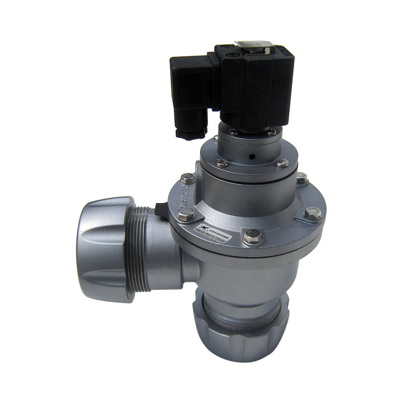
Right-angle pulse valves are widely used in conventional dust collection systems with external manifolds. Straight-through valves provide a direct airflow path that can reduce pressure losses, while submerged valves integrate into the air header to minimize external piping. Selection depends on flow capacity, installation space, and system pressure requirements.
Low-pressure pulse valves are designed to operate efficiently at reduced air pressure, while high-pressure models use components suited to higher operating loads. Diaphragms, springs, and pilot assemblies must match the valve's specified pressure range. Always verify manufacturer ratings and component compatibility to prevent poor valve response or premature failure.
Pulse valve material selection depends on temperature, corrosion exposure, and operating pressure. Nitrile (NBR) suits standard applications, while FKM and suitable TPE formulations offer alternatives for demanding temperature conditions. Aluminum valve bodies are common in general dust collection, while stainless steel or protective coatings may be preferred for corrosive and coastal environments.
Diaphragm Material | Temperature Range | Pressure Tolerance Characteristics |
|---|---|---|
Buna-N (Nitrile) | -20°C to 85°C | Standard pressure tolerance; excellent for general purpose applications. |
Viton (FKM) | -15°C to 200°C | Maintains pressure integrity in high-heat environments; resists chemical degradation. |
TPE (Thermoplastic Elastomer) | -40°C to 80°C | Superior flex life under high pressure; resists cracking in extreme cold. |
Deploying optimal pressure settings involves practical challenges. Theoretical calculations often clash with real-world facility conditions. You must proactively mitigate risks related to air quality and maintenance practices. A robust diagnostic framework ensures long-term system stability.
Water condensation is a severe implementation risk. Moisture in the air lines travels into the pilot valve. In cold weather, this water freezes. A frozen pilot cannot actuate, regardless of the available working pressure. Moisture also degrades elastomeric diaphragms over time.
Oil carryover from compressors is equally damaging. Synthetic compressor oils attack Buna-N rubber. The diaphragm swells, becomes sticky, and fails to respond to pressure differentials. This artificially alters the required pulse valve working pressure and causes erratic actuation.
Mitigation requires strict air treatment protocols. Implement proper refrigerated or desiccant air dryers. Install coalescing filters immediately upstream of the baghouse header. Establish routine blowdown procedures for the header tank to drain accumulated condensation. Clean air guarantees reliable valve performance.
Regular pulse valve maintenance helps prevent pressure-related failures and compressed air leakage. Inspect diaphragms for deformation, cracking, or wear, and check pilot solenoids and bleed holes for contamination. Monitoring valve response and promptly replacing damaged seals helps maintain stable header pressure, reduce compressor energy consumption, and extend equipment service life.
Pressure monitoring systems help identify performance issues before they cause equipment failure. Header pressure transducers track pressure drops and recovery times, while differential pressure sensors monitor filter cleaning efficiency. Combining real-time monitoring with historical data logging supports on-demand cleaning, early leak detection, and preventive maintenance.
Optimizing pulse valve working pressure helps balance filter cleaning performance and compressed air consumption. Gradually reduce header pressure within manufacturer-approved limits while monitoring baghouse differential pressure and cleaning effectiveness. The goal is to identify the lowest pressure that maintains reliable dust removal, reduces unnecessary compressor operation, and supports long-term system efficiency.
A: The standard operating range for most industrial applications is between 0.3 and 0.8 MPa (40 to 115 psi). This varies based on valve design. Submerged valves and specialized low-pressure models operate efficiently below 0.3 MPa, depending on the filter media and header configuration.
A: Low pressure prevents the diaphragm from overcoming its internal spring tension. The valve opens sluggishly, resulting in a weak air blast that fails to clean the filter. In severe cases, the valve fails to reseal and remains stuck open, continuously leaking compressed air.
A: Yes. Consistently operating at or above maximum rated pressure accelerates mechanical fatigue. It stretches elastomeric diaphragms beyond their elastic limits, leading to premature rupture. It also creates excessive shockwaves that tear filter bag seams and damage internal cages.
A: Consistent, moderate pressure provides reliable cleaning without excessive mechanical stress. Erratic pressure fluctuations or high-pressure spikes violently snap the bags against their cages. This friction destroys the fabric fibers and seams, drastically reducing the operational lifespan of the filter media.
A: Valve size determines the volume of air discharged. Larger valves release massive air volumes instantly. If the header tank is undersized, this rapid discharge causes a severe pressure drop. You must ensure the tank volume supports the valve size to maintain stable working pressure.
A: A valve typically sticks open due to low supply pressure failing to seat the diaphragm. Other common causes include debris blocking the internal bleed hole, a ruptured main diaphragm, or a malfunctioning pilot solenoid that fails to close and equalize the pressure chambers.