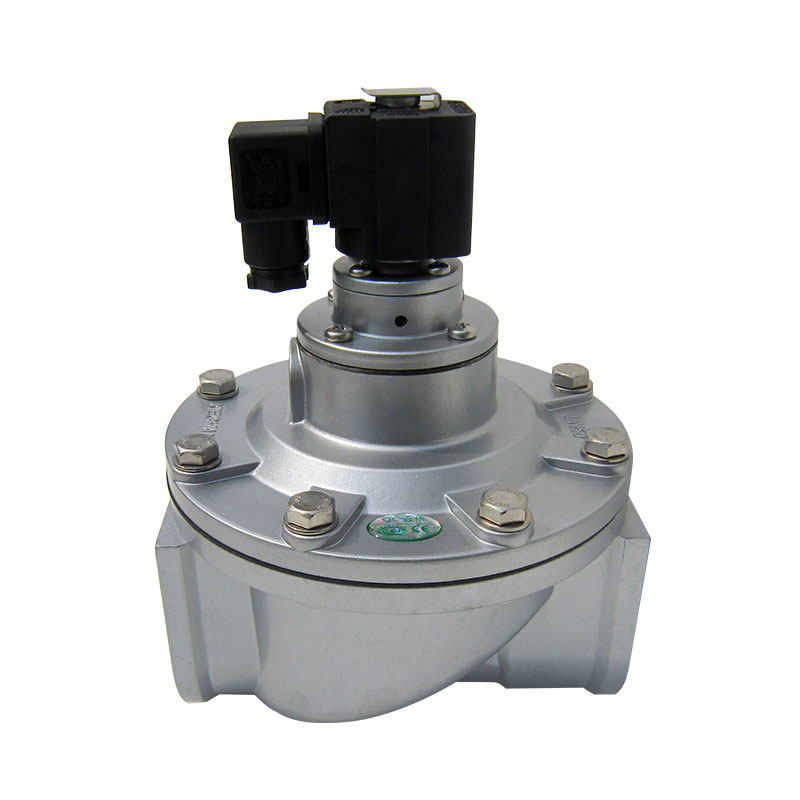
Valve geometry dictates compressed air consumption and directly controls cleaning efficiency in reverse pulse jet dust collectors. Engineers face a constant mechanical challenge on the plant floor. You must balance limited spatial footprints against the demand for high peak-flow rates. Selecting the wrong valve geometry creates severe operational problems. It leads to excessive pressure drops across the manifold. It causes poor filter cleaning and ultimately accelerates premature diaphragm failure. This technical evaluation guide helps facility managers and system engineers determine exactly when to specify straight-through designs over traditional right-angle configurations. We focus on physical layout realities, acoustic shockwave optimization, and the hard performance limits of these critical pneumatic components.
Straight-Through Pulse Valves minimize flow restriction by aligning the inlet and outlet on the same axis, offering higher flow coefficients (Cv/Kv) compared to standard right-angle valves.
Ideal straight-through pulse jet valve applications include space-constrained retrofits and systems requiring inline manifold configurations where traditional 90-degree piping is unfeasible.
Computational Fluid Dynamics (CFD) analysis proves that linear flow paths reduce kinetic energy loss, delivering a more powerful acoustic shockwave to the filter media.
Pipe layout must account for moisture drainage, resonance frequency, and maintenance access, as inline configurations can complicate diaphragm replacement if not engineered correctly.
Performance limits are dictated by maximum pressure ratings, response times, and the specific acoustic shockwave requirements of the filter media being cleaned.
Table of Contents
Toggle
How Straight-Through Pulse Valves Work & Air Flow Features
Air Flow Route and Pressure Loss Test Results
Airflow behaves predictably when forced through restrictive geometries. Traditional right-angle valves force compressed air to execute a sharp 90-degree turn inside the cast aluminum body. This sudden directional shift creates massive internal turbulence. It generates parasitic drag and kinetic energy loss before the air even exits the valve. A linear flow trajectory eliminates this sharp diversion. Computational Fluid Dynamics (CFD) analysis demonstrates a significant reduction in internal turbulence when air travels along a single axis. The straight-through design preserves the kinetic energy of the compressed air burst, allowing the system to utilize the full force of the stored header tank pressure.
This preserved energy directly influences the acoustic shockwave delivered to the blow tube. Filter cleaning relies on a rapid pulse peak and a controlled decay. The linear burst generates a sharper, faster pressure spike. This rapid spike maximizes the acoustic impact against the filter media. The inertial and acoustic effects of this linear burst improve the resonance frequency. A stronger resonance frequency easily dislodges stubborn, sticky particulate cakes from deep within the filter pleats. You achieve better cleaning using less compressed air volume per cycle.
The sequence of a linear pulse event happens in milliseconds. Understanding this sequence helps engineers troubleshoot poor cleaning performance:
The timer board sends an electrical signal to the solenoid coil.
The solenoid armature lifts, opening the pilot exhaust port.
Air trapped above the main diaphragm vents to the atmosphere, creating a pressure differential.
The header tank pressure forces the main diaphragm upward, opening the linear flow path.
Compressed air rushes straight through the valve body and into the blow tube at near-sonic velocities.
The solenoid de-energizes, closing the pilot port and allowing pressure to equalize, which seats the diaphragm back against the main orifice.
Straight-Through vs. Right-Angle and Integral Valves
Flow coefficients dictate valve performance and system sizing. Engineers use Cv (imperial) or Kv (metric) values to measure flow capacity. When comparing valves of the identical port size, Straight-Through Pulse Valves consistently yield higher flow coefficients. The absence of an internal 90-degree corner reduces flow restriction. You can push more air through a straight valve in the same millisecond timeframe. This allows you to clean longer filter bags or larger cartridge arrays without upsizing the entire manifold system.
Mechanical actuation differences also play a major role in reliability. Straight-through designs feature incredible internal simplicity. They contain fewer flow-disrupting internal components. The diaphragm actuates linearly, opening the main exhaust port with minimal mechanical resistance. You must also evaluate the actuation methods. Integral solenoid configurations mount the electrical coil directly on the valve body. Remote pneumatic pilot valves separate the electrical components from the main valve body. Remote pilots work exceptionally well in straight-through layouts where space is tight. They remove bulky electrical housings from the immediate manifold area, protecting sensitive electronics from vibration and heat.
Performance Metric
Straight-Through Valves
Right-Angle Valves
Flow Path Geometry
Linear (Inlet and outlet on same axis)
90-Degree Turn
Flow Coefficient (Cv/Kv)
High (Minimal internal restriction)
Moderate (Turbulence at the corner)
Space Requirement
Compact inline footprint
Requires vertical and horizontal clearance
Acoustic Shockwave Profile
Rapid peak, high kinetic energy
Slightly dampened peak, slower rise time
Maintenance Accessibility
Often requires partial pipe disassembly
Easy top-cover removal without pipe disruption
Typical Pressure Drop
Very Low
Moderate to High
Common Use Cases for Straight-Through Pulse Valves
Space-Constrained Dust Collector Retrofits
Facility upgrades often force engineers to work within existing structural footprints. You cannot simply expand the steel housing of an older baghouse when it sits tightly between structural columns or existing process equipment. When evaluating straight-through pulse jet valve applications, space constraints drive the primary engineering decision. Inline valve geometry allows for significantly tighter spacing between blow tubes. You can pack more filter bags or cartridges into the exact same square footage.
Mounting valves directly parallel to the header tank provides a distinct mechanical advantage. Narrow enclosures prohibit the bulky, protruding profile of right-angle valves. The linear design hugs the manifold tightly. This configuration maximizes filter density inside the collector. You increase the total filtration surface area without altering the external dimensions of the dust collector housing. We frequently see this application in cement plants and foundries where older, undersized dust collectors must be retrofitted to handle increased production loads without expanding the physical footprint of the equipment.
High-Volume, Low-Pressure (HVLP) Cleaning Systems
High-Volume, Low-Pressure (HVLP) cleaning systems use large airflow volumes at relatively low pressures to remove dust from filter media. Straight-through pulse valves minimize flow resistance and pressure loss, helping deliver effective cleaning pulses at reduced operating pressures. Their high flow capacity supports efficient dust removal, lower energy consumption, and reduced mechanical stress on filter elements when properly matched to the system.
Specialized Pneumatic Conveying and Material Handling
Straight-through pulse valves are also used in pneumatic conveying, silo discharge, and bulk material handling systems. Rapid air pulses help clear material blockages, reduce powder bridging, and improve flow through hoppers and chutes. Their compact inline design supports flexible installation and efficient airflow delivery in industrial material handling applications.
Pipe Layout and Header Tank Configuration Rules
Manifold Integration and Blow Tube Alignment
Proper manifold and blow tube alignment ensures efficient airflow and prevents mechanical stress on pulse valve connections. Flexible couplings can accommodate minor misalignment and vibration, while correctly sized supports help maintain piping stability. Pulse timing should allow sufficient header pressure recovery between cleaning cycles to ensure consistent filter cleaning and reduce compressed air waste.
Minimizing Flow Restrictions in Upstream Piping
Properly sized compressed air piping is essential for maintaining stable header pressure and effective pulse cleaning. Undersized pipes, restrictive fittings, and insufficient air storage can cause excessive pressure drops and weaken cleaning pulses.
Optimizing pipe diameter, manifold capacity, and air supply recovery helps maintain consistent valve performance and reduce unnecessary compressed air waste.
Orientation and Moisture Drainage Considerations
Correct valve orientation and moisture management help prevent corrosion, diaphragm damage, and cleaning failures. Install valves according to manufacturer recommendations and provide drainage at low points in the compressed air system. Automatic drains, suitable air treatment, and freeze protection help reduce moisture accumulation and maintain reliable operation.
Working Limits and Performance Restrictions
Maximum Pressure Ratings and Response Times
Pulse valve pressure ratings and response times directly affect cleaning efficiency and equipment reliability. Operating beyond manufacturer-specified pressure limits can damage diaphragms and seals, while slow valve response may increase compressed air consumption. Selecting valves with suitable operating pressure ranges and rapid opening and closing characteristics helps optimize filtration performance.
Diaphragm Wear and Maintenance Accessibility
Diaphragm durability and maintenance access are important considerations when selecting straight-through pulse valves. Although optimized airflow designs may reduce internal flow resistance, compact inline piping can complicate diaphragm replacement. Incorporating accessible fittings, unions, and sufficient service clearance helps simplify maintenance and reduce downtime.
Temperature Extremes and Hazardous Environments
Pulse valve materials and electrical components must be suitable for the operating environment. Nitrile diaphragms are commonly used in standard applications, while compatible FKM or silicone materials may be selected for specific temperature conditions.
For dust collection systems handling combustible materials, additional safety measures may be necessary. The OSHA guidance on combustible dust hazards discusses explosion risks, hazard identification, and appropriate protective measures for industrial dust-handling equipment.
Electrical equipment, valve components, and installation methods should meet the applicable hazardous-area requirements and local regulations.
Diaphragm Material
Temperature Range
Best Application Environment
Nitrile (Buna-N)
-4°F to 185°F (-20°C to 85°C)
Standard ambient dust collection, woodworking, grain handling.
Viton (FKM)
-20°F to 400°F (-29°C to 204°C)
High-heat environments, foundries, chemical processing, asphalt plants.
Assessing Long-Term Energy Savings vs. Initial Layout Costs
Straight-through pulse valve systems may require higher initial investment due to precise piping alignment and specialized fittings. However, their optimized airflow design can reduce pressure losses and compressed air consumption, potentially lowering compressor energy costs. Improved cleaning efficiency may also extend filter life and reduce maintenance expenses, providing long-term operational value.
Evaluating System Scalability and Compliance
Inline pulse valve configurations support modular expansion through additional manifold sections while maintaining a compact installation footprint. When planning system upgrades, engineers should ensure adequate maintenance access and compliance with applicable dust collection, electrical, and combustible dust safety requirements. Proper layout design helps improve scalability without compromising system safety or filtration performance.
Conclusion
Measure your existing header tank clearance to confirm inline valve compatibility before ordering components.
Calculate the required Cv/Kv value based on your specific blow tube diameter and total filter media area.
Specify slip-fittings or union joints in your piping design to guarantee future maintenance access for diaphragm replacements.
Upgrade to Viton diaphragms if your operating temperatures exceed the standard limits of Nitrile rubber.
Consult with a pneumatic systems engineer to verify that your timer board settings match the acoustic resonance of a linear valve burst.
FAQ
Q: What is the main advantage of a straight-through pulse valve over a right-angle valve?
A: The primary advantage is a significantly reduced internal pressure drop. The linear flow path eliminates the 90-degree turn, resulting in a higher flow coefficient (Cv/Kv). This geometry delivers a faster, more powerful acoustic shockwave to the filter media, improving cleaning efficiency while using less compressed air.
Q: Can straight-through pulse valves be mounted in any orientation?
A: No. You must avoid bottom-mount installations. Mounting them at the bottom of a header tank allows moisture and condensation to pool directly on the diaphragm. This causes electrical shorts and material degradation. Mount them horizontally or slightly above the manifold centerline.
Q: How do you calculate the correct size for a straight-through pulse valve?
A: Sizing requires matching the valve's Cv/Kv value to the blow tube diameter and the total filter media area it must clean. You must also factor in the operating pressure. Pneumatic sizing calculators help determine the exact volume of air required per pulse cycle.
Q: Should I use an integral solenoid or a remote pilot for inline pulse valves?
A: Remote pilots are generally preferred for tight inline layouts. They remove bulky electrical housings from the manifold, saving space. Remote pilots also improve electrical safety in hazardous environments by allowing you to place the solenoids in a separate, explosion-proof control cabinet.
Q: What causes premature diaphragm failure in inline pulse valves?
A: Premature failure stems from three main causes. Excessive air pressure ruptures the rubber. Moisture or solid debris in the air supply degrades the elastomer and blocks the bleed holes. Extreme temperatures outside the rating of standard Nitrile/Buna-N cause the material to become brittle or melt.
Q: Are straight-through valves suitable for high-pressure dust collection systems?
A: They are suitable up to their maximum pressure ratings, which typically cap at 120 to 125 PSI. If your system requires pressures exceeding 125 PSI, you risk diaphragm rupture. In extreme high-pressure scenarios, specialized heavy-duty piston valves might be required instead of standard diaphragm designs.
Q: How does pipe layout affect the acoustic shockwave in a dust collector?
A: Pipe bends, restrictive fittings, and undersized supply lines dampen the cleaning pulse. Every restriction absorbs kinetic energy before the air reaches the filters. Linear valve designs and straight blow tubes preserve this energy, ensuring a sharp, effective acoustic shockwave dislodges the dust cake.