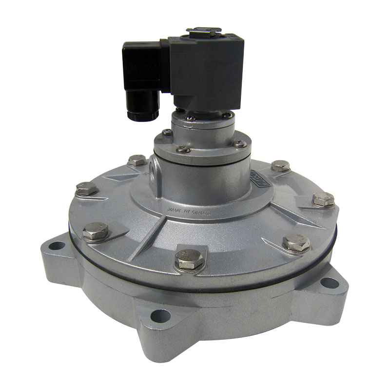
Compressed air drives the pulse-jet cleaning mechanism in modern industrial baghouses. It represents one of the most expensive utilities in heavy facilities like cement plants, foundries, and steel mills. The cleaning system must maintain continuous baghouse operation without wasting this resource. The valve dictates the exact volume and velocity of air released into the filters. Getting this specification right determines the operational success of the entire dust collection system.
Incorrect sizing introduces severe operational risks. Undersizing the valve leads to inadequate dust cake removal. The weak pulse fails to fracture the dust layer, causing differential pressure to spike across the tubesheet. Filter blinding inevitably follows, forcing unexpected system shutdowns. Oversizing creates a different set of destructive problems. It causes premature bag failure by subjecting the fabric to violent expansion forces. It consumes excessive compressed air, strains the pneumatic system, and forces compressors to run continuously. Engineers must apply a systematic approach to valve specification. The process transitions from basic baghouse design criteria—like filtration area and dust load—to specific pneumatic calculations, blowtube configurations, and valve performance metrics.
Key Takeaways
Pulse valve size selection must be mathematically matched to the total internal volume of the filter bags per row and the overall filtration area to achieve the necessary cleaning shockwave.
Operating pressure paradigms (high-pressure/low-volume vs. low-pressure/high-volume) dictate both the valve style and the required flow coefficient (Cv or Kv).
Blowtube diameter, orifice sizing, and header tank capacity are inextricably linked to valve size; altering one without the others degrades cleaning efficiency.
Table of Contents
Toggle
How Pulse Valves Affect Baghouse Performance
Mechanics of Pulse-Jet Cleaning
Pulse-jet cleaning systems use short bursts of compressed air to create reverse airflow inside filter bags, dislodging accumulated dust into the collection hopper. Unlike traditional shaker or reverse-air systems, pulse-jet cleaning can operate without stopping filtration.
Fast valve response and appropriate pulse duration are important for effective dust removal and efficient compressed air use.
Defining Success Criteria for Valve Sizing
Correct pulse valve sizing helps maintain stable differential pressure, extend filter bag life, and minimize compressed air consumption. Undersized valves may provide insufficient cleaning force, while oversized valves can waste air and increase filter stress. Proper selection balances cleaning performance, energy efficiency, and equipment durability.
Performance Metric
Properly Sized Valve
Undersized Valve
Oversized Valve
Differential Pressure
Stable within design range
May increase due to poor cleaning
May fluctuate due to excessive cleaning
Filter Bag Life
Supports normal service life
Dust buildup may shorten service life
Excessive pulse stress may accelerate wear
Air Consumption
Optimized air usage
May require frequent cleaning
Higher air consumption per pulse
Cleaning Performance
Consistent dust removal
Weak or incomplete cleaning
Potential over-cleaning
Key Factors That Decide Pulse Valve Size
Filter Bag Dimensions, Total Volume, and Filtration Area
Filter bag length, diameter, quantity, and filtration area directly influence pulse valve sizing. Larger or longer bags require sufficient reverse airflow for effective dust removal, while more bags per row increase the total cleaning demand. Engineers should calculate bag dimensions, evaluate the air-to-cloth ratio, and consider induced airflow when determining the required valve capacity.
Row Configuration and Blowtube Capacity
Bag row configuration, header volume, and blowtube diameter affect compressed air distribution during pulse cleaning. Insufficient header capacity or undersized blowtubes can cause pressure losses and uneven cleaning across filter rows.
Matching valve flow capacity with the blowtube and manifold design helps maintain consistent pulse performance throughout the baghouse.
System Operating Pressure and Dust Load
Operating pressure and dust characteristics determine the airflow and cleaning energy required from a pulse valve. Lower-pressure systems may require higher-flow valve configurations, while sticky, moist, or dense dust can demand more intensive cleaning. Valve selection should account for pressure range, dust properties, filtration conditions, and manufacturer performance specifications to ensure reliable operation.
How to Calculate and Select Pulse Valve Size
Calculating Flow Requirements (Cv and Kv Factors)
The Flow Coefficient defines the capacity of the valve. In imperial units, we use Cv. It measures the gallons of water per minute that pass through the valve at a 1 psi pressure drop. In metric units, we use Kv. It measures cubic meters per hour at a 1 bar pressure drop. These metrics form the foundation of precise pulse valve size selection. You cannot size a system accurately without knowing the exact flow coefficient of the hardware.
You must match the valve flow rating to the required air volume per pulse. We measure this in standard cubic feet per minute (SCFM) or normal cubic meters per hour (Nm³/h). Calculate the total air required to pressurize the bag row. Divide this volume by the valve open time (typically 100 to 300 milliseconds). This gives you the peak flow rate requirement. A valve might only be open for a tenth of a second, but during that time, it flows air at a massive rate.
Select a valve with a Cv or Kv rating that exceeds this peak flow rate. Account for the pressure drop across the valve body. A high Cv indicates less internal restriction. This allows more air to reach the blowtube quickly. Never size a valve based solely on connection thread size. A 1.5-inch valve from one manufacturer might have a drastically different Cv than a 1.5-inch valve from another. Always verify the flow coefficient against your calculated pneumatic requirements.
Matching Valve Size to Header and Blowpipe Dimensions
Proper pulse valve sizing ensures efficient compressed air delivery and consistent filter cleaning. Valve outlets should match the blowpipe dimensions and airflow requirements, while smooth pipe transitions help minimize pressure loss.
Key Sizing Considerations
Valve Outlet Size: Match the blowpipe diameter and required airflow capacity.
Installation Distance: Minimize unnecessary piping between the valve and blowpipe.
Airflow Efficiency: Ensure sufficient pulse pressure and volume for effective filter cleaning.
Common Valve Sizes and Application Ranges
Valve Size
Metric Equivalent
Typical Applications
3/4"–1"
20–25 mm
Small bin vents and silo filters
1.5"
40 mm
Standard modular dust collectors
2"
50 mm
Industrial dust collectors with heavier dust loads
3"+
75 mm+
Large baghouses and long-filter applications
Actual valve selection depends on filter dimensions, number of bags per row, operating pressure, valve flow coefficient (Cv), and cleaning requirements.
Different Types of Pulse Valve Designs
Right-Angle vs. Straight-Through vs. Full-Immersion Valves
Different pulse valve designs offer distinct advantages in airflow performance, installation flexibility, and maintenance accessibility.
Valve Type
Key Features
Suitable Applications
Right-Angle
90° airflow path, easy installation and maintenance
Standard industrial dust collectors
Straight-Through
Direct airflow path, reduced flow resistance
Compact systems and custom piping layouts
Full-Immersion
Integrated into the air header, minimal external piping
High-flow and demanding pulse-jet systems
Selection Tip: Choose the valve configuration based on available installation space, airflow requirements, maintenance access, and system design.
Diaphragm Material and Actuation Selection
Diaphragm material and actuation configuration should be selected according to operating temperature, compressed air conditions, maintenance accessibility, and environmental requirements.
Integral solenoid valves simplify installation and wiring, while remote pilot systems allow electrical components to be positioned separately from the main valve body.
For dust collection systems handling combustible materials, the OSHA guidance on combustible dust hazards highlights the importance of identifying explosion hazards and implementing appropriate protective measures.
Valve components and electrical equipment should be evaluated for the applicable hazardous-area classification before installation.
Diaphragm Material
Temperature Range
Best Application Environment
Nitrile (Buna-N)
-4°F to 185°F
Standard ambient dust collection
Viton
-20°F to 400°F
High heat, chemical exposure, asphalt
TPE
-40°F to 150°F
Extreme cold weather, outdoor silos
Conclusion
Conduct a comprehensive compressed air audit on your dust collection system to identify pressure drops during cleaning cycles.
Measure the actual differential pressure across your tubesheet and compare it against the baseline design specifications.
Inspect the first three bags in every row for mechanical wear, which indicates poorly balanced blowtube orifices.
Consult with valve manufacturers to perform computational fluid dynamics (CFD) modeling on custom blowtube designs before retrofitting.
FAQ
Q: What is the most common pulse valve size for industrial baghouses?
A: 1.5-inch and 2-inch valves serve as the industry standard for typical modular applications. Facilities use 3-inch or larger metric equivalents (75mm+) for long-bag or high-dust-load systems, such as those found in heavy cement plant operations.
Q: How does operating pressure affect pulse valve size selection?
A: Lower operating pressures require larger valve orifices. A higher flow coefficient (Cv) delivers the necessary volume of cleaning air at low velocity. High-pressure systems utilize smaller valves to achieve the required shockwave through high-velocity air delivery.
Q: Can I install a larger pulse valve to improve baghouse cleaning?
A: Do not arbitrarily upsize valves. Installing a larger valve without a correspondingly sized blowtube, orifice redesign, and sufficient header tank volume causes uneven cleaning. It often leads to severe mechanical bag damage at the front of the row.
Q: What is the difference between a right-angle and a full-immersion pulse valve?
A: Right-angle valves mount externally on the header tank and feature a 90-degree flow path, which creates a slight pressure drop. Full-immersion valves mount internally within the header tank. They offer superior flow efficiency and eliminate external piping restrictions.
Q: How do I know if my pulse valve is undersized?
A: Symptoms include persistently high differential pressure across the tubesheet and frequent filter blinding. You may also notice short bag life and weak pulse impact sounds during the cleaning cycle, even when the header tank shows adequate pressure.
Q: How does the number of bags per row impact valve sizing?
A: More bags per row require a larger total volume of air per pulse. This necessitates a larger valve and blowtube to maintain the required sonic velocity at each orifice. You must also adhere to structural limits, typically maxing out at 4 to 8 rows depending on header diameter.