The efficiency of a pulse-jet bag filter system relies entirely on the integrity of the compressed air manifold. Even minor installation flaws cause massive energy waste. Improper installation of submerged valves directly causes air leaks, pressure drops, and weak bag cleaning. This chain reaction leads to premature filter blinding, increased compressor load, and unplanned system downtime. When compressed air escapes through poorly sealed interfaces, the primary cleaning mechanism fails. Maintenance teams then get stuck in reactive troubleshooting cycles. You need a systematic, engineering-led approach to submerged pulse jet valve installation. Success requires strict adherence to tank opening tolerances, precise seal application, and rigorous post-installation checks. This ensures the pneumatic system operates exactly as designed, keeping differential pressure low and production running.
Precision in Tank Openings: The structural integrity and dimensional accuracy of the air header (tank) openings dictate the baseline performance of the submerged valve; burrs or warping will compromise the seal.
Seal Material and Placement: Selecting the correct elastomer (e.g., Nitrile, Viton) based on operating temperature and ensuring proper seating without pinching is critical for long-term pressure retention.
Torque and Alignment: Uneven fastening during installation distorts the valve body or diaphragm, leading to immediate blow-by or failure to actuate.
Mandatory Commissioning Checks: Static pressure tests and baseline pulse signature verifications are non-negotiable steps to validate installation before returning the dust collector to service.
Table of Contents
Toggle
How Submerged Pulse Valves Work in Dust Collectors
Submerged vs. Header-Mounted Configurations
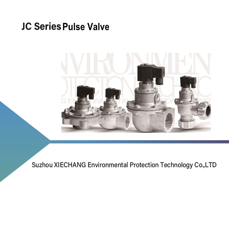
Submerged pulse valves are installed directly into the compressed air header, providing a shorter airflow path and potentially higher flow efficiency than external header-mounted designs. This configuration supports rapid air discharge and effective filter cleaning. However, proper valve positioning and secure sealing are essential to prevent compressed air leakage and maintain reliable pulse valve performance.
According to the U.S. EPA's guidance on pulse-jet fabric filter operation, pulse-jet dust collectors use short bursts of compressed air to remove accumulated dust from filter bags. Maintaining effective cleaning performance helps control pressure drop across the filtration system.
Defining Installation Success: Pressure Retention and Pulse Force
Successful submerged pulse valve installation requires reliable pressure retention and sufficient cleaning pulse force. Proper sealing prevents continuous air leakage, while stable header pressure ensures effective compressed air delivery to the filter bags. Checking for leaks and verifying pulse performance help maintain dust collector efficiency, reduce compressor energy consumption, and prevent premature filter clogging.
Tank Hole Preparation Before Valve Installation
Dimensional Tolerances and Hole Geometry
Accurate tank hole dimensions are essential for proper submerged pulse valve installation and reliable sealing. The opening must match the manufacturer's specified diameter and maintain a uniform, round shape to ensure even O-ring or gasket compression. Oversized, undersized, or distorted holes can cause uneven sealing, compressed air leakage, and premature seal failure.
Defect Type
Common Cause
Field Consequence
Corrective Action
Out-of-Round Hole
Manual plasma cutting without a guide
Uneven O-ring compression, immediate blow-by
Re-cut opening and weld a new precision-machined flange
Warped Header Wall
Excessive heat during manifold fabrication
Flat gasket fails to seat flush against the tank
Grind surface flat or replace the affected header section
Oversized Diameter
Using incorrect hole saw or drill bit
O-ring extrudes under pressure and blows out
Weld a reducer plate with the correct internal diameter
Deep Surface Scratches
Aggressive grinding during paint removal
Air channels form underneath the flat gasket
Polish the sealing surface with fine-grit abrasive pads
Surface Finish and Deburring Requirements
Proper surface preparation ensures reliable sealing during submerged pulse valve installation. Remove burrs, rust, weld spatter, and sharp edges from the tank opening to prevent gasket or O-ring damage. Smooth, clean contact surfaces help reduce compressed air leakage and improve long-term sealing performance.
Structural Integrity of the Air Header (Manifold)
Air header integrity is essential for maintaining stable pressure and reliable pulse valve operation. The manifold must have sufficient structural strength to withstand repeated pressure cycles. Before installation, inspect for corrosion, deformation, and internal debris that could damage diaphragms or block pilot passages.
Where applicable, compressed air receiver systems must also comply with relevant pressure equipment safety requirements. For reference, OSHA's compressed air receiver safety requirements address pressure gauges, safety valves, drainage, and installation considerations.
Choose and Install Seals for Pulse Valves
Evaluating Seal Materials Based on Environment
Seal material selection depends on operating temperature, chemical exposure, and compressed air conditions. Buna-N (NBR) suits general applications, FKM (Viton) offers improved heat and chemical resistance, and silicone provides flexibility in low-temperature environments. Always verify material compatibility and manufacturer temperature ratings before installation.
Gasket and O-Ring Placement Protocols
Correct gasket and O-ring placement prevents air leakage and premature seal failure. Flat gaskets require uniform compression, while radial O-rings must fit securely within their sealing surfaces. Apply a thin layer of manufacturer-approved, elastomer-compatible lubricant where recommended to prevent twisting, pinching, or damage during assembly.
Addressing Damaged Gaskets and Emergency Repairs
Damaged or compressed gaskets should be replaced rather than reused. Cracks, deformation, and loss of elasticity can compromise sealing performance. Avoid using silicone caulk as a substitute for approved pressure seals. Replacing defective components and inspecting the sealing surfaces provides a more reliable long-term solution.
Step-by-Step Guide to Install Submerged Pulse Valves
Mandatory Safety Precautions and Pre-Installation Inspection
Before installing submerged pulse valves, follow applicable Lockout/Tagout (LOTO) procedures, disconnect electrical power, isolate the compressed air supply, and verify complete depressurization. Inspect the manifold, valve opening, diaphragm, and pilot components for damage or contamination.
Confirm that the replacement valve matches the system specifications before installation.
Valve Alignment and Insertion Techniques
Proper valve alignment prevents seal damage and ensures effective pulse cleaning. Insert the valve smoothly without excessive force, position electrical connectors and exhaust ports according to manufacturer instructions, and align the blow tube with the filter openings. Correct positioning helps maintain airflow efficiency and prevents premature filter wear.
Fastening and Torque Sequencing to Prevent Distortion
Controlled fastening ensures uniform gasket compression and protects the valve body from distortion. Tighten mounting bolts gradually using an appropriate cross-pattern sequence where applicable, following the manufacturer's torque specifications. Avoid over-tightening, which can damage seals, deform valve components, and interfere with diaphragm movement.
Post-Install Testing and System Startup
Static Pressure Leak Testing
Static pressure testing verifies sealing performance before commissioning. Gradually pressurize the air header according to manufacturer procedures and inspect valve connections, gaskets, and blow tube joints. Use an approved leak-detection solution or ultrasonic detector to identify air leaks and correct any problems before normal operation.
Electrical and Pneumatic Actuation Checks
Electrical and pneumatic testing confirms that the pulse valve responds correctly to control signals. Verify solenoid voltage, inspect electrical connections, and activate the valve through the timer controller or approved test function. The diaphragm should open and close promptly without continuous air leakage or abnormal operation.
Baseline Pulse Signature Verification
Pulse pressure monitoring helps evaluate valve performance and supports preventive maintenance. Record the air header pressure drop and recovery time during normal valve activation. These baseline measurements allow maintenance teams to identify changes in diaphragm response, pilot operation, or air supply performance during future inspections.
Conclusion
Integrate the baseline pressure drop data recorded during commissioning into the facility CMMS for future reference.
Schedule a mandatory follow-up leak inspection using ultrasonic tools or soap solutions after the first 100 hours of operation to account for natural gasket settling.
Standardize the torque specifications and sequencing patterns in your standard operating procedures to prevent future distortion issues during routine maintenance.
Maintain a dedicated stock of environment-specific replacement seals to avoid emergency use of incompatible materials.
FAQ
Q: What is the difference between a submerged and a header-mounted pulse valve?
A: A header-mounted valve is installed externally on a threaded pipe extending from the air manifold. A submerged valve is installed directly into or through the manifold wall, sitting partially inside the pressurized tank. Submerged designs eliminate restrictive inlet pipes, offering higher flow rates and faster response times for more aggressive filter cleaning.
Q: What safety precautions are required before a submerged pulse jet valve installation?
A: Strict Lockout/Tagout procedures are mandatory. You must isolate the electrical power to the timer board and physically lock out the compressed air supply. You must completely depressurize the air header by opening the manual drain valve and physically verifying the absence of air pressure before loosening any hardware.
Q: How do I fix an air leak around a submerged pulse valve installation?
A: First, depressurize the system. Check the torque on the mounting bolts to ensure even compression. If the leak persists, remove the valve and inspect the O-ring or flat gasket for cuts, pinching, or compression set. Inspect the tank opening for burrs or out-of-round distortion. Replace damaged seals and re-install properly.
Q: Can I use silicone caulk to repair a pulse valve gasket?
A: No, silicone caulk is not a permanent engineering solution. While it may serve as an emergency patch to keep a system running during a shift, RTV silicone cannot withstand the long-term shockwaves and rapid pressure cycling of a pneumatic pulse system. Damaged gaskets must be replaced with proper elastomeric seals.
Q: What is the correct torque specification for pulse valve bolts?
A: Torque specifications vary strictly by manufacturer and valve size. Always consult the OEM manual for exact foot-pound or Newton-meter ratings. Regardless of the specific number, always apply torque using a star or cross-pattern sequence, tightening bolts to 50% first, then 100%, to prevent warping the valve body.
Q: Why is my newly installed pulse valve continuously leaking air?
A: Continuous leaking, or blow-by, is typically caused by debris trapped under the main diaphragm seat, preventing it from closing fully. It can also be caused by a stuck pilot solenoid armature, a blocked bleed hole in the diaphragm, or uneven torque on the valve cover that distorts the internal rubber components.
Q: How do you test a pulse valve after installation?
A: Gradually pressurize the system to operating pressure and perform a soap bubble or ultrasonic leak test around all seals. Verify the electrical signal from the timer board. Conduct a dry-run actuation to ensure the valve opens crisply and closes immediately, recording the baseline pressure drop in the header for future reference.