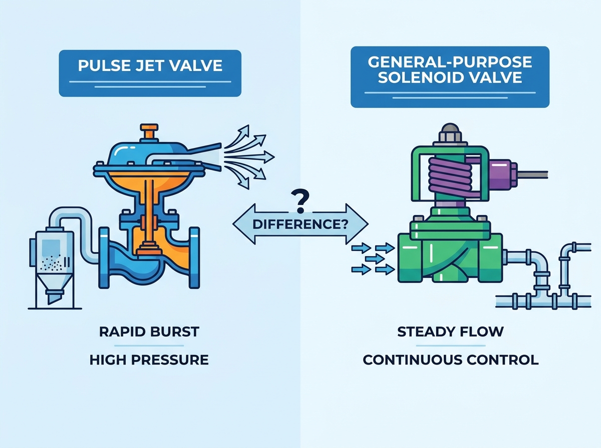
Misapplying valve technologies in industrial fluid and gas control systems introduces severe operational risks. Specifying the wrong valve type for compressed air management directly leads to inadequate system performance, excessive energy waste, and unplanned facility downtime. Engineers frequently face a dilemma: selecting the correct valve mechanism for high-velocity, short-duration air bursts versus continuous flow control. Substituting a general-purpose valve into a specialized, heavy-particulate environment guarantees premature equipment failure. It prevents adequate system cleaning and exhausts massive volumes of compressed air.
To avoid these failures, facility managers and system engineers must apply a strict technical evaluation framework. Understanding the core differences between a pulse jet valve vs solenoid valve requires analyzing flow characteristics, actuation mechanisms, structural design, and lifecycle maintenance requirements. Proper specification ensures optimal pneumatic efficiency and protects downstream equipment from catastrophic failure.
Table of Contents
Toggle
Key Takeaways
Primary Function Divergence: General-purpose solenoid valves are designed for continuous or standard on/off control and directional routing of fluids and gases. In contrast, pulse jet valves are engineered specifically for high-peak, millisecond-duration bursts of compressed air.
Structural Differences: Pulse jet valves typically feature a right-angle (90-degree) body design to optimize air acceleration and reduce pressure drop, unlike the standard inline configuration and linear operating members of most general-purpose solenoids.
Actuation Speed: A pulse valve requires exceptionally fast opening and closing times (often under 100 milliseconds) to create a shockwave for filter cleaning; standard solenoids prioritize steady-state flow over rapid shock actuation.
Application Specificity: Specifying a standard solenoid for a dust collector baghouse will result in failed filter cleaning, while using a pulse valve for standard process fluid control is an over-engineered, incompatible solution.
Defining the Baseline: Valve Topologies and Mechanisms
The General-Purpose Solenoid Valve Architecture
General-purpose solenoid valves serve as the foundational control components in modern process automation. The architecture consists of several core components. An electromagnetic coil generates a magnetic field when energized. This field acts upon a linearly operating member, typically called a plunger or armature. The plunger moves to either open or close a primary orifice within the valve body. A return spring forces the plunger back to its resting state once the electrical current ceases.
These valves operate in two primary modes, each offering unique engineering strengths for different field applications. Understanding these modes prevents misapplication in complex piping networks.
Direct-acting: The magnetic coil directly lifts the plunger off the orifice. This design requires zero minimum pressure differential to operate. It works perfectly for rapid actuation in small-scale systems, vacuum lines, or low-pressure gravity-fed loops. However, lifting the plunger against full system pressure consumes significant electrical energy, requiring larger coils for high-pressure applications.
Pilot-operated (Indirect-acting): This design utilizes the existing system pressure differential to actuate a larger diaphragm or piston. The electromagnetic coil only opens a tiny pilot orifice. The resulting pressure imbalance forces the main seal open. This method is highly efficient for high-flow applications, drastically reducing the electrical energy required by the coil. It requires a minimum pressure differential (usually around 2 to 5 PSI) to function.
Engineers classify general-purpose solenoids by their port configurations. A 2-way valve simply starts or stops flow. A 3-way valve diverts flow between two different circuits or exhausts pressure from a single-acting cylinder. Complex directional routing relies on 4-way and 5-way classifications, commonly used to drive double-acting pneumatic cylinders in automated packaging lines. Typical use cases include controlling cooling water, lubricating oil, standard compressed air, and inert gas flows across various manufacturing environments.
The Pulse Jet Valve Architecture
Pulse jet valves utilize a highly specialized architecture designed exclusively for explosive bursts of compressed air. The internal components differ significantly from standard solenoids. They feature heavy-duty, flexible diaphragms rather than rigid linear plungers. The pilot assembly can be integral to the valve body or mounted remotely in a separate NEMA-rated enclosure to protect the electrical components from harsh environments. Specialized bleed holes and exhaust ports dictate the precise timing of the pressure release.
The operational mechanism relies entirely on pressure differentials and precise internal volumes. The sequence of operation happens in milliseconds:
Compressed air enters the valve inlet from the header tank.
Air passes through a small bleed hole in the diaphragm, filling the upper chamber.
This trapped air creates downward pressure, sealing the diaphragm tightly against the main orifice.
The control timer sends a brief electrical signal to the pilot solenoid.
The pilot plunger lifts, opening the exhaust port.
Trapped air above the diaphragm vents instantly to the atmosphere.
Main line pressure below the diaphragm violently forces it upward.
A massive, instantaneous blast of air travels down the blow tube.
The pilot solenoid de-energizes, closing the exhaust port.
Air equalizes through the bleed hole, snapping the diaphragm shut.
Typical use cases revolve around heavy industrial filtration. They are the standard choice for reverse-jet dust collectors, baghouses, and cartridge collectors. They also clean gas turbine intake filters and provide the necessary air bursts for pneumatic conveying systems handling bulk dry powders like cement, flour, and carbon black.
Pulse Valve vs Solenoid Valve: Key Engineering Differences
Flow Characteristics and Cv (Flow Coefficient) Values
The flow profile represents a critical point of divergence. General-purpose solenoids deliver a steady-state flow profile. Once the valve opens, the fluid or gas reaches a continuous, stable volumetric flow rate. The system relies on this stability for consistent process control, such as maintaining a specific flow rate of cooling water to a heat exchanger. Conversely, pulse valves must deliver a high-volume, instantaneous peak flow. The goal is not continuous transfer, but a sudden, violent release of kinetic energy.
Calculating the Flow Coefficient (Cv) requires different methodologies for these two valve types. For a standard solenoid, engineers calculate Cv based on continuous volumetric flow at a specific pressure drop (usually 1 PSI for water). When evaluating a pulse valve vs solenoid valve, the Cv calculation for the pulse valve must account for optimizing a sonic shockwave. The valve must pass the maximum amount of air in the shortest possible time to generate the necessary cleaning force. A high Cv in a pulse valve means less internal restriction, allowing the air to reach sonic velocity (Mach 1) as it exits the orifice.
Response Time and Actuation Speed
Actuation speed defines the success of a pulse jet system. Millisecond response times are absolutely critical. The valve must open fully in roughly 10 to 20 milliseconds and close within 100 milliseconds. This rapid action creates a shockwave in the air. This shockwave travels down the blow tube, exits through precisely drilled holes, and violently shakes the filter media. This action dislodges the accumulated dust cake on the outside of the filter bag.
If a valve takes 50 milliseconds to open, the shockwave never forms. The result is a slow hiss of air that wastes energy and fails to clean the filter. General-purpose solenoids operate at acceptable, but generally slower, opening and closing speeds. In liquid lines, actuating a valve too quickly causes damaging hydraulic shock, commonly known as water hammer. Standard solenoids are intentionally designed to open and close at a rate that prevents this destructive pressure spike, prioritizing system safety over rapid shock actuation.
Structural Design and Port Configuration
Standard solenoids typically utilize an inline porting configuration. The inlet and outlet align on the same axis, creating a straight-through flow path. The linear plunger sealing mechanism drops directly down into this path. While effective for continuous flow, this internal geometry creates turbulence and restricts maximum instantaneous velocity.
Pulse valves almost exclusively use a right-angle (90-degree) porting geometry. The air enters horizontally from the header tank and exits vertically downward into the blow tube. This specific geometry minimizes flow restriction. It allows the expanding air to accelerate rapidly, maximizing the air blast impact. Connection types also vary significantly based on field installation requirements.
Connection Type
Installation Speed
Alignment Tolerance
Common Application
NPT Threaded
Slow
Low (Requires exact pipe lengths)
General solenoids, small pulse valves
Dresser Nut / Compression
Fast
High (Allows slip-fit adjustments)
Large baghouse pulse manifolds
Flanged
Moderate
Low (Requires precise bolt alignment)
High-pressure process solenoids
Field technicians heavily favor dresser nut fittings for pulse valves. These fittings allow for rapid installation and alignment of the blow tubes without rotating the entire 10-foot pipe or the heavy valve body, drastically cutting down maintenance time during plant outages.
Application Requirements and Selection Criteria
Selection Criteria for General-Purpose Solenoid Valves
Deploying a general-purpose solenoid successfully requires matching the valve to specific process demands. The primary requirement is precise, continuous flow control. Systems requiring multi-directional routing rely heavily on 3-way, 4-way, and 5-way solenoid configurations to manage complex pneumatic or hydraulic logic.
Media compatibility dictates material selection. Standard solenoids must handle a wide variety of fluids, corrosive gases, and high-temperature steam. This requires diverse body materials like brass, 316 stainless steel, or engineered plastics like PTFE. Furthermore, applications involving closed-loop systems or gravity-fed lines require operation in zero-differential pressure environments. Direct-acting solenoids fulfill this specific success criterion perfectly, ensuring flow regardless of upstream pressure fluctuations.
Selection Criteria for Pulse Jet Applications
Pulse jet applications demand entirely different performance metrics. The absolute primary requirement is delivering the maximum peak pressure in the shortest possible timeframe. The system relies on microsecond bursts to clean filter media effectively. A sluggish valve fails to clean the filters, leading to high differential pressure across the baghouse, which eventually chokes the entire manufacturing process.
High reliability in heavy particulate environments is non-negotiable. These valves operate in dusty, hazardous, and abrasive conditions found in cement plants, foundries, and grain silos. The internal components must resist fouling. Success also requires specific diaphragm materials selected based on ambient temperatures and chemical exposure.
Diaphragm Material
Temperature Range
Best Application Environment
Known Limitations
Nitrile (Buna-N)
-20°F to 180°F
Standard compressed air, general dust
Degrades rapidly in high heat
Viton (FKM)
-20°F to 400°F
High temp, chemical/oil exposure
Poor flexibility in extreme cold
TPE (Thermoplastic)
-40°F to 150°F
Extreme cold weather environments
Lower maximum temperature threshold
Evaluation Dimensions: Features to Operational Outcomes
Energy Consumption: Electrical vs. Pneumatic Efficiency
Evaluating energy consumption requires looking at both electrical draw and pneumatic efficiency. Electrically, pilot-operated general solenoids reduce the continuous electrical draw compared to direct-acting models. However, pulse valves exhibit minimal electrical draw overall. Because their duty cycle is measured in milliseconds, the coil remains energized for a fraction of a second, keeping electrical consumption negligible even in systems with hundreds of valves.
Pneumatic efficiency presents the actual operational challenge. Compressed air is an expensive utility. A sluggish pulse valve, or an improperly specified standard solenoid acting as a substitute, wastes massive volumes of air. If the valve lingers in the open position after the shockwave dissipates, it simply bleeds expensive air into the atmosphere. A single leaking pulse valve can waste hundreds of cubic feet per minute (CFM), forcing air compressors to run continuously. Optimized pulse valves snap shut instantly, reducing air consumption while maximizing cleaning efficiency.
Maintenance Frequency and Lifecycle Costs
Wear and tear mechanisms differ drastically. Standard solenoid linear seals wear down gradually from friction and chemical exposure. Pulse valves endure violent, repetitive actuation. The diaphragm sustains massive physical stress during every cycle. Evaluating the mean time between failures (MTBF) requires looking at diaphragm fatigue limits versus linear seal degradation. A high-quality pulse valve diaphragm should last over one million cycles before requiring replacement.
Ease of maintenance directly impacts system downtime. Modern pulse valves are designed for rapid servicing. Maintenance teams can utilize drop-in diaphragm kits. This allows technicians to replace the wearable components without removing the heavy valve body from the compressed air manifold. The field procedure is straightforward:
Lock out and tag out the compressed air header.
Bleed all residual pressure from the manifold.
Remove the top bolts securing the valve cover.
Inspect the internal bleed hole for debris or scale.
Drop in the new diaphragm and return spring.
Torque the cover bolts in a star pattern to ensure an even seal.
Environmental Durability and Compliance
Industrial environments dictate strict compliance standards. General-purpose valves typically require standard NEMA 4 or IP65 ratings to protect against dust ingress and water spray. These are sufficient for standard manufacturing floors, indoor process plants, or protected equipment rooms.
Dust collector environments present severe combustible dust risks. Fine particulate suspended in the air creates an explosive atmosphere. Pulse valves operating in these zones must carry rigorous ATEX, IECEx, or NEMA 7/9 hazardous location certifications. The electrical coils must be intrinsically safe or housed in explosion-proof enclosures to prevent catastrophic ignition. Using a standard solenoid with a basic DIN connector in a combustible dust zone violates safety codes and risks facility destruction.
Implementation Risks and Mitigation Strategies
Risk 1: Undersizing the Valve (Pressure Drop)
Selecting a valve based purely on the existing pipe size rather than the required Cv is a common engineering failure. Undersizing the valve chokes the airflow. In a pulse system, this leads to weak cleaning pulses that fail to dislodge the dust cake. In a process system, it restricts flow and starves downstream equipment.
Mitigation requires rigorous mathematical sizing. Engineers must follow a strict procedure to ensure the valve geometry supports the required velocity:
Determine the total volume of the blow tube and filter area.
Calculate the required peak flow rate to achieve a sonic shockwave.
Identify the available header pressure at the valve inlet.
Utilize manufacturer sizing charts to select a valve with a Cv rating that exceeds the calculated requirement.
Risk 2: Moisture and Debris in the Air Supply
Compressed air systems inherently generate water condensation and pipe scale. If moisture enters a pulse valve, it pools above the diaphragm. In cold environments, this water freezes, locking the valve closed or tearing the diaphragm during actuation. Debris easily clogs the tiny bleed holes, which is particularly catastrophic for pilot-operated pulse valves, rendering them permanently open or closed.
Mitigation demands strict air quality control. Implement proper upstream air filtration to catch particulate before it reaches the header tank. Install desiccant dryers to lower the pressure dew point and eliminate moisture entirely. Establish routine blowdown procedures for the air header to clear accumulated sludge. In extreme cold, install heat tracing on the valve bodies and header pipes.
Risk 3: Incorrect Voltage and Coil Burnout
Electrical failures frequently plague large valve installations. Mismatching the solenoid coil voltage with the control system output guarantees immediate failure. Furthermore, failing to account for voltage drop across long wiring runs in large baghouse installations results in weak magnetic fields. The valve may fail to open fully, or the coil may overheat and burn out trying to lift the plunger.
Mitigation involves precise electrical specification. Specify appropriate AC or DC coils matched to the control panel. Utilize transient voltage suppression to protect against power spikes. Verify that the timer board output capacity is fully compatible with the inrush current requirements of the selected coils. For long wire runs, upsize the wire gauge to minimize voltage drop across the system.
Conclusion
While both valve types utilize electromagnetic coils to control fluid or gas, their internal geometries, port classifications, and operational physics serve entirely different engineering purposes. General-purpose solenoids excel at continuous, stable flow control and complex fluid routing. Pulse jet valves are highly specialized instruments designed exclusively to unleash violent, microsecond bursts of compressed air for heavy industrial cleaning.
Selecting the correct technology requires a sequential decision framework. First, identify the media; if handling liquids or process gases, standard solenoids are required. Second, identify the flow profile; continuous routing demands standard valves, while microsecond bursts require pulse technology. Finally, identify the physical environment; clean processes allow standard ratings, while heavy particulate zones demand specialized, ruggedized equipment.
To ensure optimal system performance and prevent premature equipment failure, execute the following steps:
Audit your current pneumatic system requirements to identify areas experiencing excessive pressure drop or inadequate flow.
Calculate your exact required Cv or peak flow metrics before selecting any replacement components.
Inspect your compressed air supply lines for moisture and debris, upgrading filtration and drying systems immediately if contamination is found.
Consult with a specialized valve manufacturer or technical distributor to verify your final specification against environmental compliance standards.
FAQ
Q: Can I use a standard solenoid valve for a dust collector?
A: No. Standard solenoids lack the rapid opening speed, high-flow Cv, and right-angle geometry necessary to generate the required cleaning shockwave. Using one results in failed filter cleaning, high differential pressure, and massive compressed air waste.
Q: What is the difference between a direct-acting and pilot-operated solenoid valve?
A: Direct-acting valves use the magnetic coil to physically lift the seal, requiring no minimum pressure but using more electricity. Pilot-operated valves use the coil to open a tiny port, utilizing the system's own pressure to open the main seal.
Q: How fast does a pulse jet valve need to actuate?
A: A high-performance pulse jet valve typically opens fully in 10 to 20 milliseconds and completes its entire open-and-close cycle in under 100 milliseconds. This extreme speed creates the sonic shockwave required for filter cleaning.
Q: Why do pulse jet valves use a right-angle design?
A: The 90-degree right-angle geometry minimizes internal flow restriction. It allows the compressed air to accelerate instantly from the header pipe down into the blow tube, maximizing the kinetic energy and impact of the air blast.
Q: What causes premature diaphragm failure in pulse valves?
A: Premature failure usually stems from moisture freezing inside the valve, abrasive pipe scale tearing the rubber, chemical degradation from incompatible airborne oils, or operating the valve in ambient temperatures exceeding the specific diaphragm material's rating.
Q: Can a pulse jet valve handle liquid media?
A: No. Pulse jet valves are designed exclusively for compressed air or inert gases. Pushing liquid through a pulse valve at high speeds causes severe hydraulic shock, instantly damaging the valve internals and surrounding piping infrastructure.