Industrial dust collection efficiency relies entirely on the reliability of the filter cleaning mechanism, where compressed air management dictates both operational uptime and energy costs. Inefficient filter cleaning leads to high differential pressure (dP), premature filter media blinding, and excessive compressed air consumption. These failures drive up operational expenditures and risk regulatory compliance failures. Mitigating these risks requires a technical understanding of pulse valve mechanics. Facility managers and maintenance engineers must understand exactly what is a pulse valve to optimize their dust collection systems. This guide breaks down valve types, operational parameters, and specification criteria to ensure optimal performance in pulse-jet dust collectors.
Functionality: Pulse valves deliver high-velocity, short-duration bursts of compressed air to dislodge dust cakes from filter bags or cartridges without interrupting system airflow.
Selection Criteria: Proper specification requires matching the valve’s flow coefficient (Cv/Kv), port size, and diaphragm material to the facility’s operating temperature, chemical environment, and compressed air capacity.
Cost Implications: Oversized or undersized valves, as well as poor pulse timing, directly inflate energy costs through wasted compressed air and accelerated wear on filter media.
Maintenance Reality: Moisture and particulate contamination in compressed air lines are the primary causes of diaphragm rupture and solenoid failure, necessitating strict air quality controls.
Table of Contents
Toggle
What Is a Pulse Valve? Core Mechanics and Function
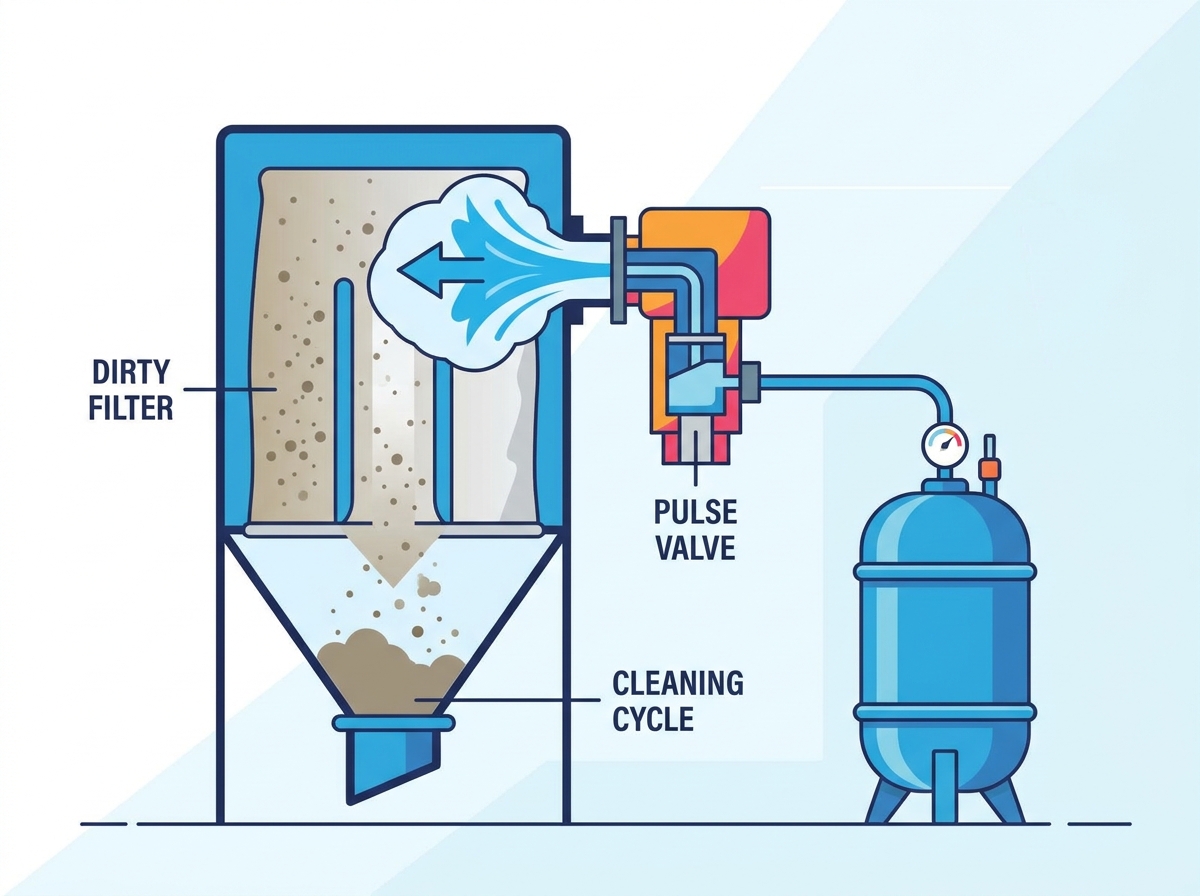
A pulse valve is a fast-acting diaphragm valve used in pulse-jet dust collectors. Controlled by a solenoid or pneumatic signal, it opens within milliseconds to release a powerful burst of compressed air from the header tank. This air pulse removes dust from the filter bags and helps maintain stable airflow.
Unlike mechanical shaker and reverse-air systems, pulse-jet cleaning can operate while the dust collector remains online. A timer board or differential pressure controller activates each valve according to a preset sequence or the pressure drop across the filters, enabling efficient cleaning with minimal production interruption.
The controller sends a brief electrical signal (typically 24VDC or 120VAC) to the solenoid pilot valve.
The solenoid coil energizes, lifting a small internal plunger and opening a pilot exhaust port.
This action vents the trapped pilot pressure from the chamber located above the main flexible diaphragm.
Because the air above the diaphragm exhausts faster than the internal bleed hole can replace it, a sudden pressure drop occurs.
The higher compressed air pressure inside the header tank forces the diaphragm open rapidly.
A high-velocity shockwave of compressed air travels down the blowpipe, exits through precisely drilled holes, and injects into the filter bags.
This shockwave is responsible for filter cake management. As the pulse of air enters the filter bag, it creates a localized area of high pressure. This induces a rapid reverse air flow, often amplified by venturi nozzles installed at the top of the bags. The filter media physically expands outward, snapping against its internal support cage. This sudden mechanical expansion fractures the accumulated dust cake on the exterior of the bag. The dust breaks apart, releases from the fabric, and falls directly into the collection hopper below. The pilot valve then closes, pressure equalizes above the diaphragm, and the main valve shuts instantly, allowing normal filtration to resume.
The Role of the Pulse Jet Valve in System Economics
Stable Differential Pressure
Reliable valve actuation removes dust from the filter bags and maintains a stable differential pressure. This supports consistent airflow while reducing fugitive dust and combustible dust risks.
Lower Compressed Air Consumption
Fast valve opening and closing deliver the required cleaning pulse without wasting compressed air. This reduces energy costs and unnecessary compressor wear.
Longer Filter Bag Life
Correct pulse timing and pressure help balance cleaning performance with media protection. Under-cleaning can cause filter blinding, while excessive cleaning may increase abrasion and premature bag damage.
Types of Pulse Valves for Dust Collection
Right-Angle Valves
Right-angle configurations are the most widely recognized design in the dust collection industry. The inlet and outlet ports are positioned at a strict 90-degree angle to each other. The inlet connects directly to the compressed air header tank, while the outlet connects to the blowpipe extending into the collector housing.
This is the standard configuration for conventional pulse-jet baghouses. They connect external square or round header tanks to internal blowpipes seamlessly. You will find these on everything from small silo bin vents to massive structural baghouses in steel mills.
Pros: They are incredibly easy to retrofit and maintain. The external mounting means maintenance teams can access the diaphragms and solenoids without entering the confined space of the collector.
Cons: The 90-degree turn introduces slight flow restrictions. This causes a minor pressure drop compared to straight-through designs, slightly reducing the peak impact of the air pulse.
Straight-Through Valves
Straight-through designs feature an inlet and outlet aligned on the exact same axis. The compressed air travels in a straight line through the valve body. The diaphragm mechanism sits perpendicular to the flow path to control the air burst.
These are heavily used in systems where space constraints dictate inline piping. They are also common in specific manifold designs where multiple valves sit in a tight linear arrangement, often fed by a single large compressed air supply line rather than a traditional header tank.
Pros: This design offers a highly efficient flow path. It experiences minimal pressure loss during actuation, delivering a stronger, more direct pulse to the filter bags.
Cons: The installation footprint can be restrictive. Piping must be perfectly aligned, making retrofits more challenging if existing pipework is slightly off-center or warped.
Manifold Mount / Submerged Valves
Manifold mount, or submerged designs, eliminate external piping entirely. The valve body is integrated directly into the wall of the compressed air header tank. In fully submerged designs, the working components sit entirely inside the pressurized tank, with only the blowpipe exiting the vessel.
These are engineered for high-performance systems requiring maximum air delivery. Heavy dust loads, sticky particulates, and exceptionally long filter bags (exceeding 20 feet) require the massive, unrestricted burst of air these units provide.
Pros: They deliver the highest peak pressure and the fastest response times. The air does not have to travel through external inlet pipes or 90-degree bends before reaching the blowpipe.
Cons: Maintenance is significantly more complex. You must completely depressurize, lock out, and often open the main header tank to access the diaphragms for replacement, which can trigger confined space entry protocols.
Valve Type
Design Profile
Primary Application
Key Advantage
Main Limitation
Right-Angle
90-degree port alignment
Standard external header tanks
Easy external maintenance access
Slight flow restriction
Straight-Through
Inline port alignment
Space-constrained inline piping
Highly efficient flow path
Strict piping alignment required
Submerged
Integrated into header tank
High-performance, heavy dust loads
Maximum peak pressure delivery
Complex maintenance access
Technical Evaluation: Sizing and Specification Criteria
Flow Rate (Cv/Kv) and Tank Pressure
Selecting the correct size requires strict adherence to pneumatic engineering principles. The primary success criterion is volume and velocity. The valve must deliver enough air to clean the entire length of the filter bag simultaneously. If the pulse is too weak, the bottom of the bag remains dirty. This reduces your effective filtration area, drives up differential pressure, and forces the system to clean more frequently.
You must evaluate the required flow coefficients carefully. The Cv (or Kv in metric systems) rating measures the flow capacity of the valve. Calculating the required Cv involves looking at the bag length, the bag diameter, and the number of bags per row. A row of fifteen 12-foot bags requires a significantly higher Cv than a row of ten 8-foot bags. Consult manufacturer flow charts to match the Cv rating to your specific blowpipe volume and hole sizing.
Pressure parameters also dictate performance. Most industrial baghouses operate between 60 to 100 PSI. However, header tank recovery time heavily impacts valve selection. If your compressor cannot refill the header tank quickly enough between pulses, the subsequent pulses will be weak. You must size the valve and the header tank volume so a single actuation does not drop the tank pressure by more than 10 to 15 PSI.
Port Sizes and Connection Methods
Standard sizing directly correlates to the blowpipe diameter. Common port sizes include 3/4", 1", 1.5", 2", and 3". A 3/4" unit might clean a small cartridge collector in a welding shop, while a 3" unit handles massive fiberglass bags in a cement kiln baghouse. Never step down a blowpipe to fit a smaller valve. This creates a severe bottleneck, destroys the pulse velocity, and renders the cleaning cycle useless.
Connection methods vary based on installation realities. Threaded connections, such as NPT or BSPT, are standard but require pipe threading equipment and thread sealant. Dresser nut, or compression fittings, allow for much faster maintenance. You simply slide the unthreaded blowpipe into the fitting and tighten the nut to compress a sealing ring against the pipe. Flanged connections are reserved for very large sizes or extreme high-pressure stability requirements where vibration might loosen threaded fittings.
Diaphragm Material Compatibility
The diaphragm is the flexible membrane that seals the air inside the header tank. Selecting the wrong material guarantees rapid failure. Buna-N, also known as Nitrile, is the standard choice for most applications. It handles ambient temperatures up to 180°F (82°C). It is highly durable, offers excellent flex life, and works perfectly for general dusts like wood, grain, or ambient welding fume.
Viton (FKM) is mandatory for high-temperature applications. If your baghouse filters exhaust from a furnace, boiler, or asphalt plant, temperatures can easily reach up to 400°F (204°C). Buna-N will melt and disintegrate under these conditions. Viton maintains its flexibility in extreme heat. It is also highly resistant to specific chemical exposures, making it ideal for chemical processing plants or environments with acid gas.
Silicone or Thermoplastic Elastomers (TPE) are evaluated for extreme low-temperature environments. Standard elastomers become brittle and crack when exposed to sub-zero temperatures. If your dust collector sits outside in a freezing climate, silicone diaphragms ensure the valve remains flexible and operational down to -40°F (-40°C).
OEM vs. Aftermarket Replacements
Maintenance budgets often drive procurement decisions. The success criterion here is balancing cost savings with guaranteed performance and system longevity. Buying cheap, unverified parts often leads to catastrophic system failures, continuous air leaks, and ruined filter bags. However, high-quality aftermarket parts can offer significant savings without sacrificing reliability.
When assessing drop-in aftermarket replacements for a pulse jet valve, you must verify exact specifications. Ensure the Cv/Kv rating matches the original equipment perfectly. Check the port alignment and center-to-center dimensions to avoid expensive piping modifications. Most importantly, ensure the aftermarket rebuild kits meet or exceed the original OEM lifecycle specifications. The elastomer quality, spring tension, and bleed hole diameter must be identical to prevent premature ruptures or sluggish actuation.
Common Installation Risks and Troubleshooting Tips
Solenoid and Electrical Faults
Electrical failures are a common source of system downtime. The primary risk is coil burnout or a complete failure to actuate. This often happens due to severe voltage drops across long wiring runs from the timer board to the collector. Water ingress is another major culprit. If water gets into the solenoid enclosure, it shorts out the coil immediately, preventing the pilot from firing.
Mitigation requires strict electrical standards. Specify appropriate NEMA or IP-rated enclosures based on your environment. If the collector is outside and exposed to rain, use NEMA 4 or 4X enclosures. If the dust is combustible, NEMA 7/9 explosion-proof enclosures are required. Verify that the pulse controller output matches the coil voltage requirements exactly. Sending 120VAC to a 24VDC coil will destroy it instantly.
Diaphragm Rupture and Leakage
A ruptured diaphragm is a severe maintenance emergency. The risk is continuous air leakage. You will hear a loud, constant hissing sound from the exhaust port or feel cold air constantly rushing down the blowpipe. This drains your main plant compressor, potentially starving other critical pneumatic equipment on the production floor. Debris from dirty air lines holding the diaphragm open causes this. Moisture degrading the elastomer is another frequent cause.
Mitigation starts at the compressor room. Mandate the installation of refrigerated or desiccant air dryers. Install heavy-duty inline particulate and moisture filters immediately upstream of the baghouse header tank. Clean, dry air is the only way to ensure a long lifecycle for your diaphragms. When replacing a ruptured diaphragm, always clean the internal seating surface of the valve body to remove rust or pipe scale.
Pulse Controller Setup and Timing Issues
Even the best hardware fails if the software is configured poorly. Incorrect "On Time" (pulse duration) or "Off Time" (frequency) creates massive operational problems. If the pulse is too long, you waste air and deplete the header tank pressure. If the frequency is too fast, you blind the bags, accelerate mechanical wear, and never allow the dust cake to settle into the hopper.
Mitigate this by implementing clean-on-demand systems. Utilize differential pressure sensors rather than continuous timer-based cleaning. The system should only clean when the dP reaches a specific high setpoint (e.g., 4.0" w.g.) and stop when it reaches a low setpoint (e.g., 2.5" w.g.). Program staggered firing sequences rather than sequential firing. Firing valve 1, then 5, then 9 optimizes header tank pressure recovery between pulses and prevents localized dust re-entrainment.
Conclusion
The pulse valve is the critical execution point of a baghouse cleaning system. Treating it as a cheap commodity rather than a highly engineered component guarantees operational inefficiencies. Proper selection, installation, and maintenance dictate the health of your entire dust collection infrastructure. When these components operate correctly, differential pressure stabilizes, compressed air costs drop, and filter life extends significantly.
Base your final procurement decisions on a strict alignment of technical specifications. Match the valve geometry to your existing header tank design. Match the flow coefficient directly to your filter area and blowpipe volume. Finally, match the elastomer material to your specific process environment and temperature range.
Take the following actionable steps to optimize your system today:
Conduct a baseline audit of your current compressed air consumption and identify continuous leaks at the header tank.
Track differential pressure trends across the baghouse to determine if your current cleaning cycle setpoints are effective.
Inspect existing air lines for moisture and particulate contamination, upgrading inline filters immediately if water is present.
Verify the voltage and NEMA rating of your current solenoid enclosures to prevent future electrical shorts.
Implement a clean-on-demand timer board upgrade to reduce unnecessary pulsing and extend filter bag life.
FAQ
Q: What is the difference between a pulse valve and a standard solenoid valve?
A: A standard solenoid valve is designed for general fluid or air control, opening relatively slowly and maintaining steady flow. A pulse valve is specifically engineered for dust collectors. It opens in milliseconds to deliver a high-velocity, high-volume shockwave of air, then closes instantly to conserve compressed air.
Q: Why are pulse-jet baghouses preferred over reverse air or mechanical shaker systems?
A: Pulse-jet systems allow for continuous, online filter cleaning. You do not need to shut down system airflow or isolate compartments to clean the bags. This continuous operation maximizes production uptime and provides a more consistent extraction volume compared to older shaker or reverse air technologies.
Q: How long should a pulse jet valve stay open during a cleaning cycle?
A: The ideal "On Time" or pulse duration is typically between 100 to 150 milliseconds. Leaving it open longer does not improve cleaning efficiency. It simply wastes expensive compressed air and depletes the header tank pressure, which weakens the subsequent pulses.
Q: What causes a pulse valve to leak air continuously?
A: Continuous air leakage is usually caused by a ruptured diaphragm or debris trapped inside the valve body. Dirt, rust, or pipe scale can prevent the diaphragm from seating properly. Moisture in the air lines can also degrade the elastomer over time, leading to tears and leaks.
Q: How do I choose the right diaphragm material for my baghouse?
A: Choose Buna-N (Nitrile) for standard ambient applications up to 180°F. Select Viton (FKM) for high-temperature environments up to 400°F or applications involving harsh chemical exposures. Use Silicone for extreme low-temperature outdoor environments where standard rubber would freeze and crack.
Q: Are aftermarket pulse valve rebuild kits as reliable as OEM parts?
A: High-quality aftermarket kits can be highly reliable and offer significant cost savings. However, you must verify that the aftermarket manufacturer uses identical elastomer grades and matches the exact dimensional tolerances of the OEM parts to ensure proper sealing and lifecycle longevity.