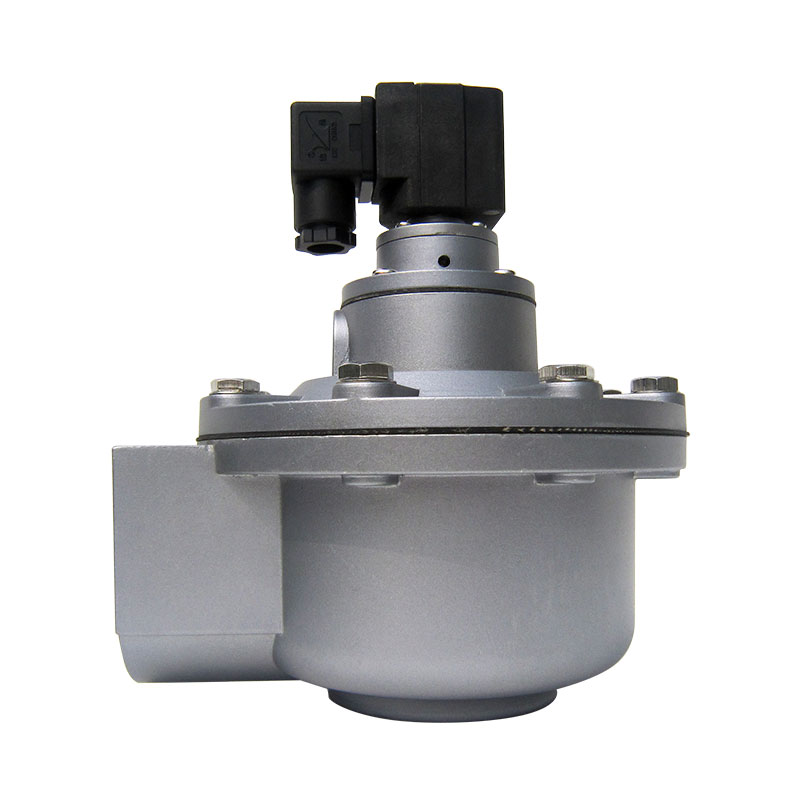
Reverse-pulse baghouses and dust collectors rely on high-energy acoustic shockwaves to dislodge particulate matter from filter media. This cleaning mechanism depends entirely on precise valve specification. Mismatched components, incorrect port sizing, or incompatible connection types lead to severe pressure drops across the system. These errors cause compressed air waste, inadequate filter cleaning, and premature system failure. Evaluating valve configurations requires a systematic, engineering-first approach. By focusing on technical specifications, port connections, and pressure requirements, engineers can ensure seamless manifold integration and optimal operational efficiency. We will break down the mechanical and pneumatic parameters required to specify the correct valve for industrial dust collection systems. You need to understand flow geometry, connection compatibility, and pressure ratings to keep your baghouse running without unexpected downtime.
Flow Geometry: Right-angle pulse valves utilize a 90-degree inlet-to-outlet path, requiring specific manifold and blow tube alignments to maximize air volume and minimize flow resistance.
Connection Compatibility: Selecting the exact right-angle pulse valve port specification (threaded, compression/dresser, or flanged) is non-negotiable for system integrity and maintenance accessibility.
Pressure & Sizing: Proper valve sizing must account for the required Cv/Kv flow factor and operating pressure ranges (typically 1–8 bar) to prevent weak pulsing or excessive air consumption.
Material Selection: Diaphragm and seat materials must align with the application's temperature and chemical exposure to mitigate premature degradation and unexpected downtime.
Table of Contents
Toggle
Understanding the 90-Degree Flow Path
Defining the Right-Angle Architecture
The structural characteristic of a right-angle pulse valve is defined by its internal flow geometry. The air inlet and outlet pipes intersect at a precise 90-degree angle. The inlet port connects horizontally to the compressed air header tank. The outlet port drops vertically, connecting directly to the blow tube. This specific orientation dictates how air travels from the reservoir to the filter media. Engineers utilize this geometry to fit valves tightly against square or rectangular header tanks. The 90-degree turn is engineered with smooth internal radii to minimize turbulence as high-pressure air rushes through the valve body. Field installations often require tight tolerances, meaning the distance between the header tank face and the blow tube centerline must match the valve's machined dimensions perfectly.
Aerodynamic Impact
This specific geometry directly affects the rapid release of compressed air. When the pilot solenoid actuates, it exhausts air from the upper diaphragm chamber. The pressure differential causes the main diaphragm to snap open instantly. Stored compressed air from the header tank forces its way through the 90-degree valve body and expands rapidly into the blow tube. This sudden expansion generates a high-velocity shockwave. The shockwave travels down the blow tube and exits through precisely drilled orifices. The resulting sonic blast creates a venturi effect, pulling secondary air into the filter bags. This combined air mass expands the filter media rapidly, dislodging the accumulated dust cake. Any restriction within the 90-degree flow path dampens this shockwave, resulting in poor cleaning performance and rapid filter blinding.
Application Suitability
The 90-degree configuration remains the industry standard for most standard blow tube setups. Square and rectangular header tanks provide flat mounting surfaces ideal for horizontal inlet connections. The vertical drop aligns perfectly with horizontal blow tubes suspended above the filter rows. This layout minimizes the footprint of the pneumatic cleaning system above the tube sheet. It eliminates the need for complex pipe routing, reducing the number of elbows and fittings that could cause pressure drops. The right-angle design provides the most direct, low-resistance path from the air reservoir to the filter media. When fabricating new header tanks, welders must ensure the stub pipes remain perfectly perpendicular to the tank face to prevent binding when installing these valves.
How to Choose Right Angle Pulse Jet Valve Configurations
Key Selection Criteria for Your Dust Collector
To make the correct specification, start by asking a fundamental question: What do I want the valve to do? Establish baseline requirements based on the specific industrial application. High-frequency pulsing is often necessary for fine, lightweight powders that blind filters quickly. High-volume, low-frequency blasts are better suited for heavy, sticky, or agglomerating particulates. Understanding how to choose right angle pulse jet valve designs requires evaluating these operational demands first before looking at physical dimensions.
Review industrial length, actuation mode, and flow requirements as an interconnected system. Modifying one parameter inevitably affects the others. A larger valve increases flow but requires more physical space and a larger header tank to prevent pressure depletion. Actuation modes must also match the environment. Integral pilot valves feature a solenoid mounted directly on the valve body. These are common in standard industrial environments where ambient temperatures remain moderate. Remote pilot valves utilize pneumatic tubing to connect the valve to a remote solenoid enclosure. Remote actuation is mandatory for highly explosive environments, extreme heat, or applications where direct valve access is hazardous for maintenance personnel.
Analyzing Right-Angle Pulse Valve Port Specifications
Selecting the correct port connection dictates system integrity and maintenance accessibility. The exact right-angle pulse valve port specification determines how the valve integrates with the manifold and blow tube. You must match the valve body to the existing pipe schedule.
Threaded Connections (NPT/BSP)
Threaded ports are standard for many small to medium-sized dust collectors. They typically utilize NPT (National Pipe Thread) or BSP (British Standard Pipe) profiles. Threaded connections provide a rigid, secure joint capable of withstanding high vibration. However, thread sealant compatibility is a strict requirement. Liquid sealants or Teflon tape must be applied correctly to prevent air leaks without contaminating the internal valve seat. In high-vibration environments, threaded connections risk galling, making future removal difficult. Threaded valves require the blow tube to be threaded, which adds manufacturing time to the manifold assembly and complicates field modifications.
Compression Fittings (Dresser Nut)
Compression fittings utilize a dresser nut and a rubber sealing ring. This design offers a distinct advantage: slip-fit connections for unthreaded blow tubes. The installer simply slides the unthreaded pipe into the valve port and tightens the nut. The rubber ring compresses against the pipe exterior, creating an airtight seal. This method significantly increases installation speed. It also provides high tolerance for slight pipe misalignment. Compression fittings absorb vibration well and make future valve replacement much faster, as no pipe rotation is required during disassembly. Installers must deburr the ends of the blow tubes before insertion to avoid slicing the rubber compression seal.
Flanged Connections
Flanged ports are engineered for large-diameter valves or high-pressure applications. They utilize a bolt circle and a flat gasket to create a rigid, leak-proof mating surface. Flanged connections are necessary when dealing with 3-inch valves, where the torque required to secure a threaded joint would be impractical. They provide structural benefits, supporting the weight of heavy blow tubes without stressing the aluminum valve body. Flanged connections ensure zero leakage under maximum operating pressures. Mechanics must tighten the flange bolts in a star pattern to ensure even gasket compression.
Sizing the Inlet and Outlet
Matching valve port diameters to existing manifold pipe schedules is a strict requirement. Port sizes typically range from 3/4", 1", 1.5", 2", up to 3". Ensure the valve inlet matches the manifold stub pipe outer diameter. Ensure the valve outlet matches the blow tube outer diameter. Mismatched sizes require reducer bushings, which introduce unwanted turbulence and pressure drops.
Connection Type
Installation Speed
Vibration Tolerance
Maintenance Accessibility
Best Application
Threaded (NPT/BSP)
Slow (Requires pipe threading)
Medium (Risk of galling)
Poor (Requires pipe rotation)
Small to medium collectors, rigid piping
Compression (Dresser)
Fast (Slip-fit unthreaded pipe)
High (Rubber seal absorbs shock)
Excellent (Slide in/out)
Systems requiring frequent maintenance
Flanged
Medium (Bolt tightening required)
Very High (Rigid mechanical bond)
Good (Drop-out design)
Large diameter valves (3"), high pressure
Sizing and Pressure Ratings: Matching Valve Capacity to Application
High, Medium, and Low-Pressure Ranges
Industrial right-angle pulse valves typically operate within a standard pressure range of 1 to 8 bar (15 to 115 psi). Operating below 1 bar generally fails to generate enough differential pressure to lift the diaphragm quickly, resulting in a slow bleed of air rather than a shockwave. Operating above 8 bar stresses the elastomer components and risks rupturing the filter media. High-pressure systems (6-8 bar) require smaller valves to deliver a crisp, fast pulse. Low-pressure systems (1-3 bar) require larger valves to deliver a high volume of air to compensate for the lack of velocity.
Engineers must use specialized valve design calculators to determine the required Cv or Kv flow factor. The Cv factor represents the volume of water in gallons per minute that will flow through the valve with a 1 psi pressure drop. In pneumatic terms, a higher Cv indicates greater air volume delivery. Proper sizing ensures the valve delivers the required flow volume without starving the manifold. If the valve is too large for the header tank, a single pulse will deplete the reservoir, causing weak subsequent pulses and triggering low-pressure alarms on the dust collector control panel.
Internal Component and Actuator Sizing
The internal mechanics of the valve must match the required port size and flow capacity. You cannot simply scale up a small valve design and expect it to perform efficiently at a 3-inch port size.
Single vs. Double Diaphragm
Valves under 1.5 inches typically utilize a single diaphragm. The pilot solenoid exhausts the small volume of air above the diaphragm quickly enough to achieve a fast opening time. However, larger port sizes (1.5 inches and above) require double diaphragms. A single large diaphragm possesses too much surface area and mass. The small pilot orifice cannot exhaust the air fast enough, resulting in a sluggish opening. Double diaphragm valves solve this using a pneumatic relay system. The pilot solenoid vents a small secondary diaphragm. This secondary diaphragm opens a much larger exhaust port, which rapidly vents the main diaphragm. This engineering logic ensures large valves achieve the millisecond response times required for effective shockwave generation.
Seat, Stem Packing, and Actuator Harmony
Selecting the right overall valve size is the final touch in system design. The valve body size must perfectly align with the chosen seat, stem packing, and actuator designs. Internal tolerances between the diaphragm assembly and the valve seat determine the sealing efficiency. A mismatched actuator will fail to lift the diaphragm fully, restricting flow. High-cycle longevity depends on these components working in absolute harmony. The actuator must possess enough electromagnetic force to overcome the internal spring tension and static air pressure instantly.
Follow these steps when sizing your valve capacity:
Calculate the total volume of the header tank to ensure it holds enough compressed air for a single pulse without dropping below 50% of its starting pressure.
Determine the total surface area of the filter media cleaned by a single blow tube.
Cross-reference the filter area with the manufacturer's Cv flow charts to find the minimum required valve size.
Verify that the plant's compressed air compressor can recover the lost volume before the timer board triggers the next valve in the sequence.
Installation and Integration
Orientation and Installation Direction
Physical installation realities heavily influence valve selection. Valves should ideally be mounted with the solenoid upright. In compressed air systems, moisture and particulate debris inevitably travel through the piping. If a valve is mounted inverted (solenoid pointing down), gravity forces condensation and debris into the pilot tube and armature tube. This accumulation causes the armature core to stick, leading to continuous air leakage or complete valve failure. Upright installation ensures moisture drains away from the sensitive electromagnetic components. If horizontal mounting is unavoidable, install moisture traps and inline filters upstream of the header tank.
Industrial Length and Spatial Constraints
Assess the face-to-face dimensions, known as the industrial length, before specification. The valve must physically fit within the existing manifold spacing without requiring extensive pipe modifications. Measure the exact distance between the header tank stub and the blow tube inlet. Ensure the chosen valve matches this gap. Furthermore, ensure adequate clearance exists around the installed valve. Maintenance personnel require physical space to access the bolts for future diaphragm replacement and solenoid servicing. Cramped installations lead to neglected maintenance, stripped bolts, and extended downtime during routine rebuilds.
Electrical and Environmental Specifications
Evaluate the electrical voltage requirements of the facility. Standard options include 24VDC, 110VAC, and 220VAC. Ensure the solenoid wattage matches the output capacity of the dust collector timer board. Overloading the timer board with high-wattage solenoids causes electrical failure and blown fuses.
Assess the required NEMA or IP enclosure ratings based on the specific operating environment. Indoor, climate-controlled facilities may only require basic dust protection. Outdoor installations exposed to rain and washdown procedures require IP65 or IP67 ratings to prevent water ingress. Facilities processing combustible dusts like flour, coal, or wood mandate ATEX or hazardous location certifications. Installing standard solenoids in explosive dust environments violates safety codes and creates severe ignition risks. Always route solenoid wiring through liquid-tight flexible conduit to prevent wire chafing against the metal collector housing.
Installation Risks and How to Avoid Them
Common Sizing and Connection Failures
Incorrect specification leads directly to mechanical and process failures. Understanding these risks is necessary for system longevity and maintaining proper airflow at the dust source.
Undersizing
Undersized valves restrict airflow, leading to weak pulses. A weak pulse fails to generate the necessary shockwave to expand the filter bag fully. Dust remains trapped deep within the filter media. This causes a rapid increase in differential pressure across the baghouse. The extraction fan works harder to pull air through the blinded filters, reducing overall suction at the dust source. Undersizing ultimately forces premature filter replacement and increases the electrical load on the main blower motor.
Oversizing
Oversized valves present equally severe risks. They deliver an excessive volume of air at high velocity. This wastes expensive compressed air. More critically, the massive shockwave causes excessive mechanical stress on the filter cages and media. Bags flex violently and tear against the metal cages. Oversized valves also cause rapid depletion of header tank pressure. If the compressor cannot refill the tank before the next pulse sequence, subsequent cleaning cycles fail, leading to uneven cleaning across the tube sheet.
Connection Blowouts
Connection blowouts occur primarily with compression fittings if installation protocols are ignored. If blow tubes are not properly secured to the collector walls, the force of the pulse can push the tube out of the dresser nut. The pipe must be inserted to the correct depth past the rubber seal. Failure to secure the blow tube results in catastrophic air leaks and immediate loss of cleaning power. Installers must use U-bolts or custom brackets at the far end of the blow tube to lock it in place against the thrust of the air pulse.
Material and Maintenance Trade-offs
Selecting the right materials directly impacts maintenance frequency and operational uptime. You must evaluate the physical environment before selecting internal components.
Material Selection
Standard Nitrile (Buna-N) diaphragms offer excellent performance in typical ambient environments. However, they degrade rapidly when exposed to high temperatures or aggressive chemicals. For high-heat applications up to 200°C, Viton (FKM) diaphragms are mandatory. Extreme low-temperature environments require specialized silicone blends to prevent the elastomer from becoming brittle and shattering under pressure. While specialty elastomers require a higher initial investment, they drastically reduce maintenance cycles and prevent sudden diaphragm ruptures during production runs.
Maintenance Accessibility
Consider the labor required for future maintenance. Hard-piped threaded valves are difficult to remove. Technicians must often cut pipes or dismantle entire manifold sections to replace a single threaded valve body. In contrast, flanged or dresser-nut valves allow for rapid removal. Technicians simply loosen the bolts or compression nuts and slide the valve out. This accessibility translates to significant labor savings during routine diaphragm rebuilds and minimizes system downtime. When designing a new system, always prioritize connections that allow single-valve removal without disturbing adjacent pipework.
Conclusion
Measure your existing manifold stub pipes and blow tube outer diameters using digital calipers to confirm exact port dimensions before ordering.
Calculate your required Cv flow factor based on the filter media surface area and header tank volume to prevent undersizing or oversizing.
Specify Viton (FKM) diaphragms if your baghouse operates above 120°C or handles chemically aggressive particulates.
Request dimensional drawings from the manufacturer to verify the industrial length fits your current header tank spacing without requiring pipe modifications.
FAQ
Q: What is the defining characteristic of a right-angle pulse valve?
A: The defining characteristic is the 90-degree orientation between the inlet and outlet ports. This specific geometry is designed for mounting horizontally on square or rectangular header tanks while feeding air vertically down into horizontal blow tubes, minimizing turbulence and maximizing shockwave velocity.
Q: How do I determine the correct right-angle pulse valve port specification?
A: Measure the outer diameter of the blow tube and the manifold stub connection. Match these measurements to standard NPT/BSP thread sizes, compression nut inner diameters, or flange bolt patterns specified by the valve manufacturer.
Q: Can I replace a threaded pulse valve with a compression fitting type?
A: Yes, provided the manifold has the appropriate nipple and the industrial length fits the existing gap. The blow tube must be smooth, unthreaded, and perfectly match the outer diameter requirements of the compression nut and rubber seal.
Q: What pressure range is standard for right-angle pulse jet valves?
A: Most industrial right-angle pulse valves are engineered to operate efficiently between 1 and 8 bar (15 to 115 psi). The exact optimal pressure depends on the diaphragm design, pilot configuration, and the specific dust characteristics.
Q: How does valve sizing affect dust collector performance?
A: Sizing dictates the volume and velocity of the air pulse. Incorrect sizing leads to either inadequate dust cake removal (causing high differential pressure) or wasted compressed air and mechanical damage to the filters. It must balance with proper seat and actuator selection.
Q: What is the difference between single and double diaphragm pulse valves?
A: Single diaphragms are used for smaller valves (under 1.5 inches). Double diaphragms feature a main and a secondary diaphragm. They are used in larger valves to reduce the volume of air the pilot must exhaust, ensuring a faster, crisper pulse response.