Industrial baghouses and dust collection systems rely on precise pneumatic sequencing to maintain airflow. The component dictating this efficiency is the pulse controller. Outdated or failing controllers lead to continuous, unnecessary pulsing. This results in massive compressed air waste, premature filter media degradation—specifically blinding or tearing—and potential EPA or OSHA compliance violations due to poor particulate capture. Upgrading or properly specifying a dust collector pulse controller requires understanding its operational mechanics. You must evaluate continuous versus on-demand cleaning and align the hardware with plant SCADA systems and environmental targets. When you get this right, you stop wasting expensive utility air and extend the life of your filter bags. We see facilities burn through thousands of dollars in compressed air simply because a timer board is set incorrectly. Fixing this starts with knowing exactly how the controller interacts with your pneumatic manifold and solenoid valves.
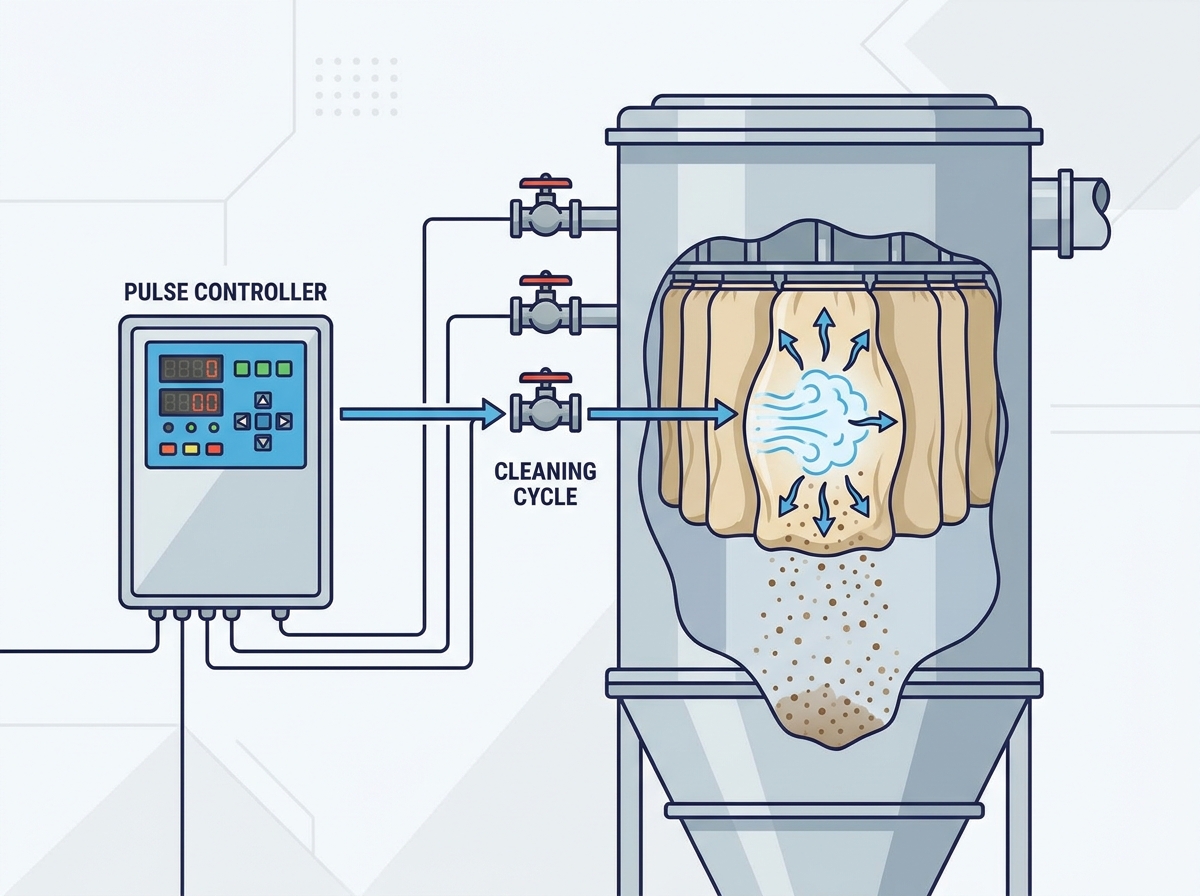
Core Function: A dust collector pulse controller acts as the brain of a pulse-jet baghouse, sending electrical signals to solenoid valves to release bursts of compressed air that clear dust cake from filter media.
Continuous vs. On-Demand: Upgrading from a standard sequential timer board to a Differential Pressure (dP) controller can reduce compressed air consumption by up to 40% while extending filter life.
Evaluation Criteria: Selecting the right unit requires matching output pin counts to valve quantities, ensuring appropriate NEMA/IP enclosure ratings for the operating environment, and verifying PLC integration capabilities.
Implementation Reality: The most common failure points are not the controllers themselves, but moisture in the air lines causing solenoid failure, or mismatched pulse durations leading to incomplete cleaning.
Table of Contents
Toggle
The Role of the Dust Collector Pulse Controller in Baghouse Systems
Defining the Component
A pulse controller is a solid-state timer or microprocessor-based device built for industrial filtration environments. It manages the cleaning cycle of a pulse-jet dust collector. Instead of relying on manual operators to blow down filters, this device automates the process. It processes inputs and outputs to dictate the exact timing, sequence, and duration of compressed air bursts. Older units used mechanical rotary switches. Modern boards use digital logic to read differential pressure inputs, log alarm states, and communicate with central plant networks. The device keeps the filter media permeable. This allows continuous airflow without over-stressing the fabric or cartridge substrates. You mount it near the baghouse, wire it to the solenoids, and let it manage the pneumatic cleaning cycles.
The System Architecture
You need to map the controller's position within the broader pneumatic architecture. The controller sits at the top of the command chain. You wire it electrically to a series of solenoid valves. These solenoids connect pneumatically to larger diaphragm valves mounted directly on the compressed air manifold, which we call the header.
When the controller initiates a sequence, it dictates how the compressed air travels. The air moves from the header, through the diaphragm valve, and down into the blowpipes positioned above the filter rows. The released air travels through venturi tubes or strikes baffle plates. This ensures an even shockwave distribution across the entire length of the filter bag. If the controller miscalculates the timing or sequence, the shockwave fails to dislodge the accumulated dust cake. This leads to immediate airflow restriction across the dust collector.
Success Criteria for a Controller
We measure a successful implementation by two primary metrics. First, it must maintain a stable differential pressure across the filter media. Second, it must minimize the frequency of compressed air usage. The differential pressure indicates the resistance to airflow caused by the dust cake on the filters. An optimized controller keeps this pressure within a tight, predictable bandwidth.
It achieves this stability using the absolute minimum number of pulse cycles. Every unnecessary pulse wastes expensive compressed air. It also inflicts mechanical wear on the filter media. You achieve success when the baghouse breathes easily while utility consumption remains strictly minimized.
How a Dust Collector Pulse Controller Works: Operational Mechanics
The Pulse-Jet Cleaning Cycle
The core operation revolves around executing the pulse-jet cleaning cycle. This sequence dislodges particulate matter without interrupting the main process airflow.
Signal Transmission
The sequence initiates when the microprocessor dispatches a voltage signal across the terminal block. This signal is typically 120VAC or 24VDC, depending on your facility's electrical standards. It travels through shielded conduit to the designated solenoid valve. The controller ensures this electrical impulse is sharp and consistent. Weak signals cause the solenoid to stutter or fail to open completely. You must ensure reliable signal transmission. Voltage drops over long wire runs severely impact cleaning efficiency.
Valve Actuation
Upon receiving the voltage signal, the energized solenoid coil creates a magnetic field. This lifts an internal plunger. The action bleeds a small volume of pilot air from the backside of the diaphragm valve. The sudden pressure differential causes the flexible diaphragm to snap open. This releases a high-pressure shockwave of compressed air from the header directly into the blowpipe. The controller triggers this actuation instantaneously. This ensures the resulting shockwave retains enough kinetic energy to travel the full length of the filter media.
Pulse Duration (On-Time) vs. Interval (Off-Time)
The controller manages two timing parameters: the on-time and the off-time. The pulse duration, or on-time, dictates the length of the electrical signal sent to the solenoid. You usually calibrate this between 50 and 150 milliseconds. A pulse shorter than 50 milliseconds fails to open the diaphragm valve fully. A pulse longer than 150 milliseconds wastes compressed air without adding any additional cleaning force.
The interval, or off-time, represents the dwell period between consecutive pulses. This pause allows the compressed air header to recharge to its full operating pressure. If the controller fires the next valve before the header recovers, the subsequent pulse will be weak and ineffective.
Firing Sequences
Advanced controllers let you select specific firing sequences to optimize cleaning and protect the pneumatic infrastructure. Linear firing sequences trigger the valves in numerical order. For example, it fires 1, 2, 3, 4. While simple to program, linear firing depletes the compressed air header localized at one end of the manifold.
Staggered or interleaved firing patterns distribute the air draw across the entire length of the header. A common staggered pattern is 1, 5, 2, 6, 3. This prevents localized pressure drops. It ensures every valve receives the maximum available air volume when actuated.
Online vs. Offline Cleaning Methods
The operational environment and the nature of the dust dictate your cleaning method. You must decide whether the controller should execute cleaning cycles while the system actively filters air or during isolated downtime.
Online Cleaning
In an online cleaning configuration, the controller sequences pulses while the main exhaust fan remains fully operational. Flue gas actively passes through the filters. The high-pressure shockwave momentarily overcomes the process airflow. It expands the filter bag and fractures the dust cake. The dislodged particulate falls into the hopper below. Online cleaning is standard for most industrial applications. It allows continuous production without requiring system shutdowns or complex damper sequencing.
Offline Cleaning
Certain applications require offline cleaning. Here, the controller integrates with pneumatic or electric damper controls to isolate specific baghouse compartments before pulsing. By closing the inlet or outlet dampers, the controller halts the process airflow through that specific section. This prevents lightweight or highly abrasive dust from immediately re-entraining onto the adjacent filters after being pulsed. Offline cleaning is mandatory in industries dealing with ultra-fine powders or heavy metallurgical dust. You also use it when strict emission limits require absolute particulate settling before the compartment comes back online.
Manual Cleaning Mode
Maintenance personnel frequently use the manual cleaning mode built into the controller interface. By engaging manual overrides and test buttons, you can force the controller to fire specific valves out of sequence. This function helps with maintenance diagnostics. It allows technicians to verify solenoid operation and diaphragm valve integrity without waiting for an automated cycle. You also use manual mode to clear heavy dust loads immediately following a system shutdown. This ensures the filters are clean before the next production run begins.
Solution Categories: Types of Pulse Controllers
Sequential Timer Boards (Continuous Cleaning)
The most basic iteration of this technology is the sequential timer board. It executes a continuous cleaning loop based strictly on programmed time intervals. Once powered, the board fires valve one, waits for the programmed off-time, fires valve two, and continues this pattern indefinitely. It operates completely blind to the actual conditions inside the baghouse. It ignores whether the filters are heavily loaded with dust or completely clean.
This continuous cleaning mechanism works best for single-unit dust collectors, small standalone bins, or predictable dust loading environments where the process runs at a constant rate. Facilities executing budget-constrained retrofits often default to sequential boards due to their low initial procurement cost and simplified wiring requirements.
However, the drawbacks are significant. Because the board pulses continuously regardless of need, it generates high compressed air waste. The constant flexing of the filter media accelerates mechanical wear. This leads to premature bag failure and increased replacement frequency.
To address the inefficiencies of continuous cleaning, the industry shifted toward Differential Pressure (dP) controllers. These units utilize a built-in or external pressure transducer to monitor the pressure drop across the clean and dirty sides of the baghouse plenum. The controller relies on operator-defined high and low setpoints to dictate the cleaning cycle.
When the dust cake builds up and the resistance reaches the high dP setpoint, the controller initiates the pulsing sequence. It continues firing valves until the dust cake clears and the pressure drops to the low setpoint. At this point, the controller halts the cleaning cycle and enters a standby mode. This on-demand mechanism is the optimal choice for large-scale industrial baghouses, variable dust load processes, and facilities prioritizing energy efficiency.
While dP controllers require a higher initial capital expenditure and slightly more complex calibration involving pressure tubing installation, the trade-offs favor long-term operational savings. By only pulsing when necessary, these controllers drastically reduce compressed air consumption and significantly extend the operational lifespan of the filter media.
Feature
Sequential Timer Boards
Differential Pressure (dP) Controllers
Cleaning Trigger
Fixed time intervals
High/Low pressure setpoints
Air Consumption
High (pulses continuously)
Low (pulses only when needed)
Filter Wear
Accelerated due to over-cleaning
Minimized
Best Application
Small bins, constant dust loads
Large baghouses, variable dust loads
Specifying the Right Controller
Valve Compatibility and Output Capacity
Specifying the correct hardware begins with an accurate assessment of the baghouse's physical configuration and the total number of required outputs.
Pin Count Sizing
You must calculate the required number of outputs based on the baghouse blowpipe configuration. A controller must have at least as many output pins as there are diaphragm valves on the manifold. Standard boards typically offer 10, 20, or 32 outputs. We recommend specifying a board with a few spare outputs. This accommodates future modifications or serves as backup channels if a specific terminal block fails.
Networked vs. Standalone
The scale of the dust collection system dictates the networking requirements. Single-board controllers work perfectly for standalone units with a limited number of valves. Large multi-module baghouses require master/slave networked configurations. In this setup, a single master controller monitors the differential pressure and dictates the sequence. Multiple slave boards mounted locally near the valves execute the electrical firing. This reduces long, expensive conduit runs and simplifies troubleshooting.
Expansion Capabilities
Facilities anticipating future growth should evaluate controllers featuring modular expansion boards. Instead of replacing the entire master unit when adding a new baghouse compartment, technicians snap an expansion module onto the existing DIN rail and connect it via a ribbon cable. This modularity protects the initial hardware investment and reduces the downtime associated with system upgrades.
Environmental Protection and Enclosure Ratings
The physical environment surrounding the dust collector dictates the necessary protective enclosure for the sensitive electronic components.
NEMA/IP Standards
Selecting the appropriate NEMA or IP enclosure rating prevents premature board failure. Standard indoor applications may only require a basic NEMA 12 dust-tight enclosure. Outdoor installations exposed to rain and washdowns demand NEMA 4 watertight housings. If the environment contains corrosive gases or chemicals, NEMA 4X fiberglass or stainless-steel enclosures are mandatory. In facilities handling combustible dusts like grain, sugar, or aluminum powder, you must specify NEMA 7/9 explosion-proof enclosures. This prevents internal electrical arcing from igniting the surrounding atmosphere.
Temperature Tolerance
Extreme ambient temperatures require specific hardware modifications. Controllers mounted outdoors in freezing climates must include built-in thermostatically controlled heaters. This prevents condensation from freezing on the circuit board. High-heat environments demand adequate ventilation and conformal-coated circuit boards. Conformal coating involves applying a thin polymeric film over the electronic components. It protects them from moisture, thermal shock, and corrosive airborne particulates.
SCADA Integration and Compliance Tracking
Modern industrial facilities require data integration between peripheral equipment and central control rooms to monitor performance and ensure environmental compliance.
Communication Protocols
Evaluating communication protocols is a required step in the specification process. Basic integration might only require a standard 4-20mA analog output to transmit the real-time differential pressure reading to a central PLC. More advanced facilities utilize Modbus RTU, Modbus TCP, or Ethernet/IP connectivity. These digital protocols allow the SCADA system to monitor individual valve performance, adjust high/low setpoints remotely, and track the exact number of cleaning cycles executed per shift.
Emissions Reporting
Environmental regulatory bodies often require detailed operational logs to verify that air pollution control equipment functions correctly. Advanced controllers feature internal memory that logs dP trends, pulse frequencies, and alarm histories. This data satisfies Title V air permit reporting requirements. By exporting this historical data, plant managers prove to inspectors that the baghouse maintained optimal pressure drops and that any fault conditions were addressed immediately.
Common Implementation Risks and How to Prevent Them
Common Failure Modes and Troubleshooting
Even the most robust electronic systems encounter operational hurdles. Establishing a clear troubleshooting framework minimizes downtime and prevents unnecessary component replacement.
Electrical Shorts and Surges
Industrial environments experience voltage spikes and electrical noise. These surges easily blow fuses or fry the internal microprocessors of the controller. A common failure point occurs when water ingresses into the solenoid conduits. This creates a dead short that travels back to the terminal block. Mitigating these risks requires installing proper surge protection devices on the incoming power supply. You must utilize drip loops on all conduit connections and ensure all enclosure seals remain intact after maintenance inspections.
Diagnosing a Faulty Pulse Controllerr
When the cleaning cycle fails, technicians must execute a step-by-step diagnostic framework to isolate the issue. Diagnosing a faulty pulse controllerr begins with verifying the input voltage at the main power terminals. If power is present but the board is unresponsive, check the primary glass fuses. Next, use a digital multimeter to verify the output signals at the terminal blocks during a firing sequence. If the multimeter registers the correct voltage drop but the valve fails to fire, the issue lies downstream in the wiring or the solenoid itself. Technicians should also test the manual override functions to bypass the automated logic and inspect the pressure tubing connected to the dP sensor for blockages or condensation buildup.
Here is a standard diagnostic sequence for field technicians:
Measure incoming line voltage at the main terminal block.
Inspect the glass or ceramic fuses on the circuit board for continuity.
Engage the manual test button to force a firing sequence.
Measure the output voltage at the specific valve pins during actuation.
Disconnect the pressure tubing and blow compressed air through the lines to clear moisture.
The "Stuck Valve" Syndrome
A frequent misdiagnosis occurs when operators confuse a failed controller output with a mechanically stuck diaphragm valve. If a valve continuously leaks air, the controller is rarely at fault. Debris or moisture in the compressed air line has likely compromised the rubber diaphragm. This prevents it from sealing against the valve seat. To differentiate between the two, technicians should disconnect the electrical wiring to the suspect solenoid. If the valve continues to leak air, the problem is entirely mechanical. The diaphragm kit requires replacement.
Optimization and Calibration Realities
Installing new hardware is only the first step. Proper calibration achieves the desired operational efficiencies.
Header Starvation
One of the most common calibration errors is setting the off-time interval too short. Operators often assume that faster pulsing equals better cleaning. If the interval is too brief, the compressed air tank cannot fully recharge between cycles. This leads to header starvation. It results in weak, ineffective pulses that fail to clean the bags while simultaneously draining the plant's compressed air capacity. You must calibrate the off-time based on the specific volume of the header and the recovery rate of the plant's air compressor.
Baseline dP Calibration
When installing a new dP controller or replacing all the filter bags, operators must establish a proper baseline pressure drop before setting the high and low cleaning thresholds. New filters require a conditioning period to build a primary dust cake. This naturally increases the baseline resistance. If you calibrate the high setpoint too low during this initial phase, the controller enters a continuous cleaning loop. This strips away the necessary primary dust cake and causes premature media wear. Observe the baseline over several days of normal production before locking in the final setpoints.
Cost vs. Value: Justifying the Upgrade
Compressed Air Economics
Calculating the return on investment for upgrading from a continuous timer to an on-demand dP controller relies heavily on compressed air economics. Compressed air is one of the most expensive utilities in any manufacturing plant. A sequential timer pulsing every 10 seconds consumes a massive volume of air over a 24-hour period, regardless of whether the filters actually need cleaning. By switching to on-demand cleaning, facilities often see a 30% to 40% reduction in pulse frequency. This directly translates to reduced electrical load on the plant's air compressors. It yields substantial monthly utility savings that quickly offset the initial purchase price of the new controller.
Filter Replacement Frequency
Optimized pulsing directly impacts the physical lifespan of the filter media. High-performance filter bags manufactured from PTFE membranes, aramid fibers, or specialized fiberglass are significant capital investments. Every time a pulse shockwave hits the bag, the fabric flexes and strikes the internal metal cage. Continuous over-cleaning accelerates this mechanical stress. It leads to premature thread failure and bag blinding. By utilizing a dP controller to pulse only when necessary, facilities drastically reduce this mechanical wear. This extends the life of expensive filter sets by months or even years.
Maintenance Labor Reduction
The hidden value of advanced controllers lies in the reduction of maintenance labor. Older sequential boards require manual baghouse inspections to verify operation. Modern controllers equipped with diagnostic LED indicators, remote alarm capabilities, and SCADA integration allow maintenance teams to monitor the system from the control room. Instead of climbing to the top of the baghouse daily to listen for firing valves, technicians receive automated alerts if a solenoid fails or if the differential pressure exceeds the threshold. This shift from reactive troubleshooting to proactive monitoring frees up valuable maintenance hours for other plant operations.
Conclusion
Audit your current baghouse differential pressure trends to establish an accurate operational baseline.
Calculate your existing compressed air usage to identify potential utility savings from an on-demand system.
Map your existing solenoid voltage and total valve quantity to determine the exact output pin count required.
Consult with a pneumatic controls specialist to specify the appropriate replacement board and enclosure rating for your environment.
FAQ
Q: What is the standard pulse duration for a dust collector pulse controller?
A: The standard pulse duration, or on-time, ranges between 50 and 150 milliseconds. This brief window fully opens the diaphragm valve and releases a high-pressure shockwave. Programming a duration longer than 150 milliseconds wastes compressed air. The valve remains open after the initial shockwave travels down the blowpipe, providing no additional cleaning force.
Q: How do I know if my pulse controller is bad?
A: Symptoms of a failing controller include continuous high differential pressure despite the system having power, no audible pulsing sounds from the baghouse, or repeatedly blown fuses on the circuit board. If the manual test buttons fail to actuate the valves, or if the LED output indicators fail to illuminate during a sequence, the board likely requires replacement.
Q: Can I upgrade a continuous timer board to a dP pulse controller?
A: Yes, upgrading is a standard retrofit process. You purchase a dP controller unit and physically install pressure tubing. Connect one tube to the dirty air plenum below the tube sheet and the other to the clean air plenum above the tube sheet. The new controller uses these inputs to monitor resistance and trigger cleaning on demand.
Q: What voltage do dust collector pulse controllers use?
A: Controllers operate on standard input and output voltages of 120VAC, 24VDC, or 240VAC. You must match the controller's output voltage to the existing solenoid coil rating. Sending 120VAC to a 24VDC solenoid destroys the coil. Sending 24VDC to a 120VAC solenoid fails to create the magnetic field necessary to open the valve.
Q: Why is my dust collector pulsing continuously?
A: Continuous pulsing usually stems from three causes. The system utilizes a basic sequential timer set to a continuous loop. A dP controller has a blocked or disconnected pressure line causing false high readings. Or, the high dP setpoint is reached but the baghouse cannot recover because the filter bags are permanently blinded with dust.
Q: What is the difference between a pulse controller and a diaphragm valve?
A: The pulse controller is the electronic brain of the system. It processes logic, monitors pressure, and sends the electrical voltage signal. The diaphragm valve is the heavy-duty mechanical component mounted on the air header. It physically opens upon receiving the pneumatic pilot signal, releasing the volume of compressed air into the filter bags.